• Steel Soldiers now has a few new forums, read more about it at: New Munitions Forums!

  • Microsoft MSN, Live, Hotmail, Outlook email users may not be receiving emails. We are working to resolve this issue. Please add support@steelsoldiers.com to your trusted contacts.

Allison M916 + Mk48 Cab = 6x6 "FEMTT"

M920

Member
892
25
18
Location
chama/nm
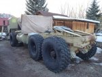
What is the plan to "fill in" all that space that now resides where the engine hood and cab used to be?
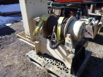
Of course there is still an engine where the hood used to be and it is getting a new one as we speak....the area where the cab was previously located at, is now shared by the 45,000 pound DP winch and the Wajax knuckle boom. This does free up 12 feet of bed space on the rear of the frame for the interchangable 'Modules'.
 
Last edited:

M920

Member
892
25
18
Location
chama/nm
It is starting to look like a truck again....

Hmmmm, I finished painting the cab today and started to hook up the steering, when all of a sudden it hit me like a brick....I finally figured out why they use a different type of yoke for the steering stub shafts than for all the other driveshaft setups!!!
The yokes, that I got for my steering, were NOT the steering type yokes.

I always figured the reason for the clamping bolt and the corresponding groove in the shaft on the steering yokes were for added safety, so the yoke could not slip off the shaft even if the bolt were to come loose.
Since in my setup the stubshafts were "trapped", I felt that securing the yokes on the shafts with the set screws, using locktite would be more than sufficient.

What I did not think of, is the fact that on most transmission shaft installations the shaft only gets torque in one direction. This lets the yoke settle against the keyway and the set screw is there to keep it all tight.

On a steering stub shaft on the other hand, the torsional forces may alternate back and forth thousends of times, while driving down a bumpy road! It is then pretty easy to imagine, that over time the set screw even thought locktited in place, will start to wear in to the shaft and in the process letting the yoke develop play within the limitations of the keyway!

Thus the reason for the clamping bolt on a steering yoke. In addition to clamping around the shaft tightly, it is also situated at a 90 degree angle from the keyway, so it can tighten up any play in the keyway slot!

Anyway, for me it was back to the drawing board. I was able to "cannibalize" two steering yokes with a 1" bore from my old HEMTT cab, but I could not find a 1 1/4" bore steering yoke.
Luckily my set screw type 1 1/4" yoke had a lot of "meat" on the collar and I was able to machine the bolt hole and the surfaces for the bolt head and nut in to it. I then used the chop saw to cut the slot and make it in to a clamping type steering yoke.
Catastrophy avoided!! :driver:


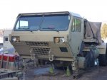
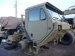
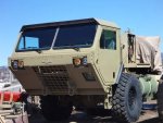
Here are some pics of the new (and hopefully improved) steering setup and the painted cab.
 

Attachments

trukhead

New member
725
5
0
Location
dane/wi
Hmmmm, I finished painting the cab today and started to hook up the steering, when all of a sudden it hit me like a brick....I finally figured out why they use a different type of yoke for the steering stub shafts than for all the other driveshaft setups!!!
The yokes, that I got for my steering, were NOT the steering type yokes.

I always figured the reason for the clamping bolt and the corresponding groove in the shaft on the steering yokes were for added safety, so the yoke could not slip off the shaft even if the bolt were to come loose.
Since in my setup the stubshafts were "trapped", I felt that securing the yokes on the shafts with the set screws, using locktite would be more than sufficient.

What I did not think of, is the fact that on most transmission shaft installations the shaft only gets torque in one direction. This lets the yoke settle against the keyway and the set screw is there to keep it all tight.

On a steering stub shaft on the other hand, the torsional forces may alternate back and forth thousends of times, while driving down a bumpy road! It is then pretty easy to imagine, that over time the set screw even thought locktited in place, will start to wear in to the shaft and in the process letting the yoke develop play within the limitations of the keyway!

Thus the reason for the clamping bolt on a steering yoke. In addition to clamping around the shaft tightly, it is also situated at a 90 degree angle from the keyway, so it can tighten up any play in the keyway slot!

Anyway, for me it was back to the drawing board. I was able to "cannibalize" two steering yokes with a 1" bore from my old HEMTT cab, but I could not find a 1 1/4" bore steering yoke.
Luckily my set screw type 1 1/4" yoke had a lot of "meat" on the collar and I was able to machine the bolt hole and the surfaces for the bolt head and nut in to it. I then used the chop saw to cut the slot and make it in to a clamping type steering yoke.
Catastrophy avoided!! :driver:


Here are some pics of the new (and hopefully improved) steering setup and the painted cab.
Brilliant!:not worthy: Good to know that factoid for any future engineering. I built a 4x4 and used to wrong joints. That 4x4 is a memory now.
 

bikeman

Well-known member
Steel Soldiers Supporter
2,894
501
113
Location
Ft. Bragg, NC
Hmmmm, I finished painting the cab today and started to hook up the steering, when all of a sudden it hit me like a brick....I finally figured out why they use a different type of yoke for the steering stub shafts than for all the other driveshaft setups!!!
The yokes, that I got for my steering, were NOT the steering type yokes.

I always figured the reason for the clamping bolt and the corresponding groove in the shaft on the steering yokes were for added safety, so the yoke could not slip off the shaft even if the bolt were to come loose.
Since in my setup the stubshafts were "trapped", I felt that securing the yokes on the shafts with the set screws, using locktite would be more than sufficient.

What I did not think of, is the fact that on most transmission shaft installations the shaft only gets torque in one direction. This lets the yoke settle against the keyway and the set screw is there to keep it all tight.

On a steering stub shaft on the other hand, the torsional forces may alternate back and forth thousends of times, while driving down a bumpy road! It is then pretty easy to imagine, that over time the set screw even thought locktited in place, will start to wear in to the shaft and in the process letting the yoke develop play within the limitations of the keyway!

Thus the reason for the clamping bolt on a steering yoke. In addition to clamping around the shaft tightly, it is also situated at a 90 degree angle from the keyway, so it can tighten up any play in the keyway slot!

Anyway, for me it was back to the drawing board. I was able to "cannibalize" two steering yokes with a 1" bore from my old HEMTT cab, but I could not find a 1 1/4" bore steering yoke.
Luckily my set screw type 1 1/4" yoke had a lot of "meat" on the collar and I was able to machine the bolt hole and the surfaces for the bolt head and nut in to it. I then used the chop saw to cut the slot and make it in to a clamping type steering yoke.
Catastrophy avoided!! :driver:


Here are some pics of the new (and hopefully improved) steering setup and the painted cab.
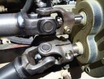
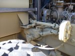
Ok, I'll admit I'm not 100% sure without seeing this first hand exactly the issue, However, the first picture attached here.... if those two U joints rotate the wrong direction, is that bolt and nut setup going to hit? It looks like if they both go clockwise about 30-40degrees they might hit, course they might miss, or not even work that way, but....
 

Stretch44875

Super Jr. Moderator
Super Moderator
Steel Soldiers Supporter
2,960
30
48
Location
Tiro, Ohio
Ok, I'll admit I'm not 100% sure without seeing this first hand exactly the issue, However, the first picture attached here.... if those two U joints rotate the wrong direction, is that bolt and nut setup going to hit? It looks like if they both go clockwise about 30-40degrees they might hit, course they might miss, or not even work that way, but....
They do rotate in opposite directions, but are 1 to 1 ratio. So if they rotate and miss, they will miss every time.
 

M920

Member
892
25
18
Location
chama/nm
They do rotate in opposite directions, but are 1 to 1 ratio. So if they rotate and miss, they will miss every time.
That is absolutely correct! I had some concerns about it myself, but the bolts are actually 90 degrees off from each other and they are not nearly as close as the photo would make you believe. Thanks everyone!
 

maddawg308

Well-known member
Steel Soldiers Supporter
10,865
762
113
Location
Appomattox, VA
Of course there is still an engine where the hood used to be and it is getting a new one as we speak....the area where the cab was previously located at, is now shared by the 45,000 pound DP winch and the Wajax knuckle boom. This does free up 12 feet of bed space on the rear of the frame for the interchangable 'Modules'.
Ah yes, I apologize - I forgot the #1 rule of reading threads: when in doubt, go back and read the first post. In other words, Duh.

Keep up the good work, Soni, this build is awesome!
 

M920

Member
892
25
18
Location
chama/nm
Ah yes, I apologize - I forgot the #1 rule of reading threads: when in doubt, go back and read the first post. In other words, Duh.

Keep up the good work, Soni, this build is awesome!
Sorry, I was not trying to be sarcastic Maddawg! It's all good, glad you like the build!
 

M920

Member
892
25
18
Location
chama/nm
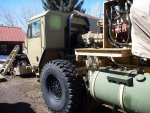
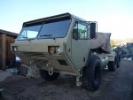
More painting and assembling....

I did some more painting today, got the front tires back on, took the winch back off for final welding and painting and hooked up the fuel lines.
I made a list of the steel needed to fabricate the new hood and the fenders. I'm having them cut the hood and fenders to size and put the necessary brakes in to them. That will save me some time, so I can concentrate on hooking up all the "vitals".
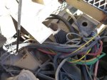
Hmmm....all the hoses and wires...looks almost like a working model of a brazilian rain forest.....:???:

Here are some of today's pics....
 

Attachments

promodhotrod

New member
49
0
0
Location
BC
Soni:
Beautiful build, I have a question from way back on your post #59, on the use of the 55000 series transfer case. I thougt the 55000 reduced in high range as well something like 2.4 to one, am I wrong on this? I was going to swap a 916 t-case in place of a 55000 to get highway speed at 1600 RPM based on it being 1 to one.
Also thanks a ton for all the detailed pics and part numbers on the steering setup, they will save me a ton of time on a similar ordeal. Your speed and quality amaze me (and make me feel old and worthless:)).
KJ
 
Last edited:

marchplumber

Well-known member
Steel Soldiers Supporter
3,802
2,834
113
Location
Peoria, Illinois
Did you by chance label all the vines from the rainforest for later replanting? OMGosh! Or are you doing it by memory? LOL! Truly, a one of a kind masterpiece!

God bless,
Tony
 

RDUKW

New member
582
11
0
Location
California
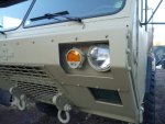
How big of a pain was it to switch out your composite lights. It looked like a fair amount of brackets on the drivers side has to be removed.

Ryan
 

M920

Member
892
25
18
Location
chama/nm
How big of a pain was it to switch out your composite lights. It looked like a fair amount of brackets on the drivers side has to be removed.

Ryan
You are not kidding!!! It took me half a day to do the driver side!!! You have to remove EVERYTHING: dash, steering wheel, steering gear box, the mounting bracket for the steering components, a small cover plate on the left under the dash, the brake pedal assembly with bracket and the throttle pedal assembly with it's bracket.
At first I tried to get away with not taking it all appart, but it became quickly obvious, that I might get the bolts off the old lights, but there was no way I was going to get them started again on the new ones. There is just no room under the dash!
In addition I had to drill new holes for the lights in order to mount them right side up, or they would have not cleared the top of the brush guard.

The good thing about doing all that, was that I found several loose bolts, four loose nuts on electrical connections and a really sharp corner of a bracket that had worn halfway through the main air supply line to the brake valve!!!!

And this all on a brand new cab?!?! Where is Oshkosh's "quality control"? :roll:
 
Last edited:

RDUKW

New member
582
11
0
Location
California
I had several bad electrical connections on my cab as well. Does your cab have the stiff steering like mine. I guess Oshkosh drilled the holes in the wrong location where the steering shaft goes through the bulkhead and it is preloading both right angle boxes. I guess what kind of quality do you expect for $26000. Oshkosh probably figured these cabs were just going to be scrapped anyways since the LVS program was dead before they shipped them.

Ryan
 

RDUKW

New member
582
11
0
Location
California
That's not good. I just checked the pics of the cab I bought, it's inverted too. :(

All of the LVS's had the lights mounted upside down including the tail lights. I'm not sure if they had a reason or if someone just screwed up on the drawings.

Ryan
 
Top
AdBlock Detected

We get it, advertisements are annoying!

Sure, ad-blocking software does a great job at blocking ads, but it also blocks useful features of our website like our supporting vendors. Their ads help keep Steel Soldiers going. Please consider disabling your ad blockers for the site. Thanks!

I've Disabled AdBlock
No Thanks