• Steel Soldiers now has a few new forums, read more about it at: New Munitions Forums!

  • Microsoft MSN, Live, Hotmail, Outlook email users may not be receiving emails. We are working to resolve this issue. Please add support@steelsoldiers.com to your trusted contacts.

Cucv m1009 drivers alternator not charging

63bravo

New member
62
0
0
Location
philadelphia pa
Having a serious issue drivers side gen not charging , all gen lights working system is stock military did the voltage checks at the regulator and excited wire checked all grounds have 12.6 volts at large red lug at rear of generator had the unit off and tested at a reputable shop . one thing I noticed when I start the vehicle the the gen 2 light ( pass) side goes off immediately , my other cucv must have a slight kick of the throttle. One more thing all batteries are new and have undergone load testing , also I noticed the glow plug resistor is bypassed if this plays into this gen issue , gen 2 is working fine 27.5 volts
 

Warthog

Moderator
Super Moderator
Steel Soldiers Supporter
13,774
232
63
Location
OKC, OK
GEN2 is actually a 12v alternator also. It just combines voltage with GEN1. Long story. The stickies cover it.

Now to your problem. How long have you had the truck? Have you made any changes? Did this issue just start?

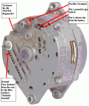
Is GEN1 (drivers side) a stock unit? Does it have two large terminals on it? (see picture). If so is the ground terminal grounded to the engine?

Alternator - labeled.gifDSC02431.JPG
 
Last edited:

63bravo

New member
62
0
0
Location
philadelphia pa
It's the stock generator and yes it's grounded to the engine block ,I just purchased it last week , of course he didn't tell me about this , the truck is stock , the pic is the same gen that's on the truck , the only mod I see is the glow plug resistor is bypassed , and 12 volts is directly feed from the relay , I bought the truck off e bay , private owner. One more thing it also reads battery voltage on drivers side gen at the 12 volt lower lug , the upper is 27.5. Sorry I meant to say the pass side gen
 
Last edited:

Warthog

Moderator
Super Moderator
Steel Soldiers Supporter
13,774
232
63
Location
OKC, OK
Sounds like you have a multimeter and know how to use it.

Okay lets test some items.

Truck off.

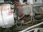
Remove the excitor wire plug and check voltage at the small red wire. Should be 12v. The brown wire should be zero volts with the key off and 12v with the key on.

What is the condition of the plug and the two terminals in the alternator? I have seen many trucks that require a good cleaning or even a new plug. (about $5 at the parts house). The terminals in the plug may also need to be tightened.

Remove ground wire and clean the connections at both ends. The terminal at the engine sometimes corrodes.

The large red wire runs to the diamond shaped 12v terminal block on the firewall. Sounds like it is okay along with the fusible link.
 

63bravo

New member
62
0
0
Location
philadelphia pa
Did the checks on the plug key on key off , all was correct readings , going to clean the ground and the terminal plug spades , a little about me , mechanic in the guard and as my regular job also , 25 years working , I'll let you know tonight after work what the outcome is , thank you for the help , wish me luck
 

63bravo

New member
62
0
0
Location
philadelphia pa
Generator drivers side : voltage readings , plug on top red wire 12 volts key on and key on , exciter wire key off no volts key on and running 2.4 volts same readings on the passanger side generator cleaned connectors check some of the grounds , also when I had my volt meter on the front battery it went too 13.2 volts while running , but when I turn the lights on it drops down to 11.7 volts , I'm at a dead end with this ..
 

Warthog

Moderator
Super Moderator
Steel Soldiers Supporter
13,774
232
63
Location
OKC, OK
Just to clarify your last post. The small brown wire on GEN1 (drivers side) is showing 2.4v with the key on and when running?

If so there is an issue with the voltage feed for this wire.

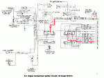
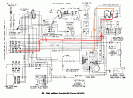
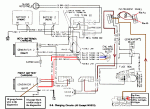
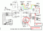
The path for the brown wire for the GEN1 exciter circuit is this:

Power is from the very top heater fuse.
power travels to the #5 pin of the instrument cluster
thru the cirguit board, the GEN1 light bulb to pin #8 of the cluster
out pin #8 to the firewall plug
thru the firewall plug to pin#1 on the GEN1 plastic plug

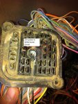
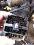
I have seen the GEN1 circuit not function properly because of dirty connections at the firewall plug along with dirty connections at the GEN1 idiot light.

Clean the bulb and socket of the GEN1 light, split the firewall plug and clean with Electrical Contact Cleaner and an old toothbrush and clean the 2pin plug at the alternator.

You will need to check the ohms/voltage readings along the path.

Make sure you read the first few pages of Chapter 2 Troubleshooting Section of the TM 9-2320-289-20 technical manual. It will explain how to read the diagrams, wire colors and sizes and how to tell what the firewall plug diagram means.

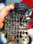
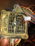
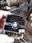
E-01 12v Feed.gifE-03 - Blower Circuit.gifE-04 - BlowerFuse.gifE-09 - GEN 1.gifE-20 - blower.gifGEN1 excitor - cabin side.jpgGEN1 excitor - firewall side.jpgGEN1 Fuse.jpgGEN1 plug - cabin side.jpgGEN1 plug - firewall side.jpg
 
Last edited:

63bravo

New member
62
0
0
Location
philadelphia pa
31 dec 2013 18:30 hours, generator# one was a no go on the charging output, as per ordered ,worthog advised removing and cleaning bulkhead main harness connector too fuse block, before cleaning the contacts and all spade termanils #1 generator voltage was 12.6 volts indicating a no go on the charging output , after servicing the bulkhead connections voltage output at # one generator is 14.7 volts, indicating a go on the repair . nothing follows in report .. thank you worthog your a high speed battle buddy !!!!!!
 

Warthog

Moderator
Super Moderator
Steel Soldiers Supporter
13,774
232
63
Location
OKC, OK
I don't know what GM used on the firewall connector but after 25+ years it turns into a black goo. Makes for poor contact.

Glad I could help out.
 

63bravo

New member
62
0
0
Location
philadelphia pa
Well came out this morning and the same thing gen 1 not charging , did the voltage checks again 12 volts when running at both wires in the plastic plug atop the generator , went over the bulkhead plug again cleaning and testing once more removed fuse block cleaned all spade connections , still no charge , but one strange thing I noticed last night some reason after removing and cleaning the bulkhead plug the glow plugs stopped working not even the wait too start light worked , But the generator would charge perfectly , than once the glow system started working again the generator stopped charging , next I'm going too remove the dash and start power probing the harness , and checking relays etc
 

cpf240

Active member
1,479
5
38
Location
Free in Northern Idaho
I did not see it mentioned, and no reason why it would have been, really, but has the GP relay / solenoid been changed recently? The wrong GP relay / solenoid can cause issues with GEN1, as I recall. The GP relay / solenoid *MUST* be an isolated-ground part. No continuity between the small terminals and the mounting brackets.
 

63bravo

New member
62
0
0
Location
philadelphia pa
Yes the guy I bought it from replaced it , looks bran spanking new , it really stinks she runs so good and starts right up even on the coldest day , I just can't believe last night it was charging great but the glow plugs were not working , lol I'm going to check out that new relay to see if the ground is isolated , thank for the help I'll post too let u know and progress
 

63bravo

New member
62
0
0
Location
philadelphia pa
i just checked my glow plug relay its grounded too the body via the mounting bracket is this correct , and if not where does the ground go and should it be isolated ?
 

doghead

4 Star General /Moderator
Staff member
Super Moderator
Steel Soldiers Supporter
26,246
1,178
113
Location
NY
So, you have continuity between one or both small terminals to the shiny metal mounting ears?

If so, that is the wrong relay.

Your GPs will be on all the time.

There are a few different relays you can buy/use. GP109 and ST85 come to mind. This should be listed in the wiki or stickies also.
 
Last edited:

doghead

4 Star General /Moderator
Staff member
Super Moderator
Steel Soldiers Supporter
26,246
1,178
113
Location
NY
So, that is the wrong relay. (your gps have been powered on whenever the key was on) this would be why your D/S alt has had a constant load and why the front battery was low.

You now need to test all of your glow plugs, remove and visually inspect your controller card(clean terminals with a pencil eraser), and replace the relay with the correct relay.
 
Top
AdBlock Detected

We get it, advertisements are annoying!

Sure, ad-blocking software does a great job at blocking ads, but it also blocks useful features of our website like our supporting vendors. Their ads help keep Steel Soldiers going. Please consider disabling your ad blockers for the site. Thanks!

I've Disabled AdBlock
No Thanks