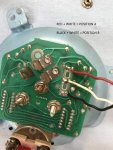
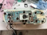
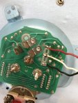
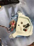
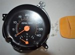
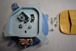
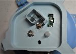
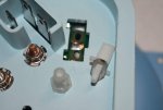
Here are some photos detailing where I needed to cut the stock dash, and how the unit is wired up. You will need to purchase a tachometer adapter from Widget Man.
They can be found on E Bay under CUSTOM-PROGRAMMED-TACH-ADAPTER
The unit will need a ratio of 1 : 5.33, with a 12 Volt output. 1.5 millisecond blanking time.
When you wire in the tach, do not tap into the ignition 12+ wire in dash wiring harness, when the glow plugs cycle, it kills power to the dash, so the tach will read zero when the glow plugs are lit or cycling.
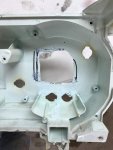
Here is where it hits and where I had to cut out, you do not need to cut the circuit board. I used a dremmel with a cutting disc:
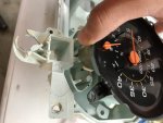
Here is the wiring. I took the diagrams off the site here, but I'm not sure if they are 100% correct. You only need to worry about the fuel sender input, ground, and hot. The tach is wired separately. I grounded to the grounding block/terminals under the dash. I did also buy a small brake light indicator and put that up between my voltage gauges. Just tap into the brake light wires if you want to add that. Fuel sender wire is terminal 18 on the board, and the pink wire in the harness. I added a second tank, so that's why I showed it switching in the video. Don't worry if your tach doesn't have the wiring plug, it will work with just normal spade terminals. The tach is clearly marked, so you won't mess it up.
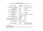
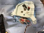
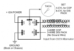

The tach has a jumper, and I broke mine. So, I soldered wires to allow me to test the different positions. Use the jumper position shown, or do what I did below and just connect the 2 wires. If you don't have the jumper, or yours is in the wrong position, be sure you take off the plastic backing plate or you will break the jumper trying to get it out. If you are installing the jumper, make sure you have the metal tab under it, or it won't complete the circuit. In the picture below, you would want the red and white wires to be connected. I was doing some testing, that's why I made it so I could change the circuit without taking the dash back out.
