• Steel Soldiers now has a few new forums, read more about it at: New Munitions Forums!

  • Microsoft MSN, Live, Hotmail, Outlook email users may not be receiving emails. We are working to resolve this issue. Please add support@steelsoldiers.com to your trusted contacts.

VIC-1 intercom panel for soft tops

US6x4

Well-known member
Steel Soldiers Supporter
1,234
2,246
113
Location
Wenatchee, WA
Given the amount of noise in the cab of these trucks and wanting to be able to talk to the person next to me without yelling I resolved to install an intercom. I looked and asked around the forum and other places but did not net much responses for what folks have done in their soft top cabs for a hard-mounted intercom so I decided to design one from scratch. The idea I had was to mount something to the tubes spanning across the top back of the cab so it would kinda be overhead but also would be behind the passengers. In addition to the intercom I thought this panel would be a good place for an interior light to shine down on the floor & dash when needed. My truck is actually an M813, but since it seems more M35's have soft tops than 5 tons and since they share a common cab/roof anyway I thought this would be a good place for the thread.

To start with I ordered a 4-person VIC-1 system from Recodefense (very nice stuff by the way) and once that arrived I had something tangible to look at and see if they would fit without smacking the riders in the head. Looks like there will be plenty of room. The 4-person system consists of (1) AM-1780 amplifier and (4) C-2298 crew control boxes - the cables to connect and power everything are not included so it's off to online auction sites to gather those up.
20190126_152822.jpg

20190126_154341.jpg

20190126_154426.jpg

20190126_154445.jpg


It took several weeks to gather all the cables and I even got one from Santa Claus during Christmas break! Now that I have the cables I can do some CAD work (cardboard-aided design) and play musical boxes to arrange them to miss everybody's head.
20190126_145007.jpg
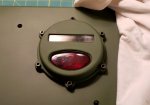
My brother and I clamped this piece of cardboard to the roof support tubes and outlined our heads while we leaned back in each of the 3 places a full grown person would sit. The way the cables connect (they are indexed) and the way they bend actually dictated how far apart the boxes would be spaced. It looked even enough so I decided not to argue with the cables. They had a natural way they wanted to lay and didn't like being forced into a different position. My buddy donated a pair of M-38 taillight covers to the project so I will make good use of them for the courtesy lights! Up next is to see what the digital CAD is going to tell us about the details of the panel and installation.

I don't have much time these days for long-winded write-ups so I'll update this as I go. Tag along to see how it will all come together (or fail)!...
 
Last edited:

US6x4

Well-known member
Steel Soldiers Supporter
1,234
2,246
113
Location
Wenatchee, WA
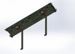
Since the plan is to laser cut all of the parts, I need to model everything up in 3D. With the VIC-1 components and the taillight covers on hand I was able to model them and then create the actual panel to match those pieces and get all of the holes cut in the correct location. I wanted to use as much GI issue components as I could to keep it looking OEM so for the courtesy lights I plan to use the 24 volt version of the good ol' 1157 dual filament taillight bulb that will give 2 levels of brightness just like the dash gauges. There will be the dimmer taillight filament and also the brighter brake light filament and I can use a 3-position rotary switch that will have OFF - DIM - BRIGHT. After I got everything modeled up this is what it should look like:

VIC-1 COM PANEL ASSY.JPG

VIC-1 COM PANEL ASSY_7.JPG

VIC-1 COM PANEL ASSY_8.JPG

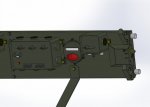
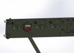
The console panel is a basic rectangular shape with 1" flanges on the top and sides and a 1/2" hem on the bottom so that nothing rubs the soft top on the bottom side. I'm going to attach the panel with 1330 u-joint u-bolts that are made for Ø1 1/16" u-joint caps since the roof tubes are Ø1". I'm going to use acorn nuts in lieu of the hex nuts on the front side to attach hanger brackets that the H-161 headsets will hang on when not in use. The bulge you see in the middle photo allows the 3-position switch and circuit breaker to be mounted transverse in the panel to save room since there is only about 1 1/8" of clearance between the soft top and the inside of the panel. When the UPS delivered the VIC-1 system and I bent down to pick up the large box I figured I will have to have some additional supports to hold up the weight of the intercom and not leave all of it for the tubes to support. I think the tubes would do just fine until I hit a bump in the road so the two vertical bars attach to the top of the cab sheet metal behind the seats. The entire panel leans forward at a 58° angle so some of the views might look skewed.

VIC-1 COM PANEL ASSY_6.JPG
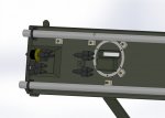
On the back side I plan to weld on tapped blocks instead of using traditional hex nuts so that components and fasteners can be removed from the front without having to get a wrench in between the panel and soft top. For the taillights I will laser out 2 rings and tap all 6 of the holes for 10-32 screws. In this screen shot you can see the 3-position switch, circuit breaker, and the wye splitters that will take the power for the dim filament and send it to both taillights and it will do the same for the bright filament.

The computer says it will work. I hope it actually works in the real world...
 
Last edited:

77 AMG

Active member
403
62
28
Location
Owingsville, KY
Question for you. Are the CVC headsets compatable with a VIC-1 set up, or do I need a different model? I can get the complete CVC headsets and cables from work.
I just looked them up, and, they are literally down the road from the farm, like maybe 10 miles down the road. ROAD TRIP tomorrow! :jumpin: (this means that I pass them every day going to and from work... Boy, do I feel silly)
 
Last edited:

US6x4

Well-known member
Steel Soldiers Supporter
1,234
2,246
113
Location
Wenatchee, WA
Question for you. Are the CVC headsets compatable with a VIC-1 set up, or do I need a different model? I can get the complete CVC headsets and cables from work.
I just looked them up, and, they are literally down the road from the farm, like maybe 10 miles down the road. ROAD TRIP tomorrow! :jumpin: (this means that I pass them every day going to and from work... Boy, do I feel silly)
Yes, the CVC helmets ( the TMs call them helmets not headsets) are shown in the VIC-1 diagrams as being interchangeable with the H-161 headsets. That's cool that you're so close. I would love to stop in and maybe get a glimpse of their restoration processes.
 

77 AMG

Active member
403
62
28
Location
Owingsville, KY
Thank you, US6X4. I call them helmets as well, not sure why I called them headsets. I will post results from the road trip later on today, for anybody that is interested, hopefully, with some pictures.
 

US6x4

Well-known member
Steel Soldiers Supporter
1,234
2,246
113
Location
Wenatchee, WA
OK, I got the pieces laser cut and had the CNC press brake fellas make all the bends I needed. I made everything out of stainless steel because of the amount of moisture in my cab and because all of the welders at work are usually set up for welding stainless. The panel, bulb holder and the switch cover are 14 gauge and the headset holders and taillight backing plate are 10 gauge. I did a fair amount of deburring and smoothing of the parts to make them look finished and make them easier to handle. All the edges get smoothed out and all the holes get chamfered.

20190329_113609.jpg

20190405_112243.jpg

20190405_112254.jpg

I polished one side of each bulb holder to a mirror finish and had the holder formed with the mirror side on the inside so that all the light will be reflected forward through the taillight lens. Then the corners and the bend relief slot get TIG welded closed. The bend relief is so the round hole for the bulb does not get deformed during the bending process.

20190403_085819.jpg

20190405_112234.jpg
The taillight backing plates get their holes chamfered and then tapped to 10-32 and get their edges smoothed out after the laser cutting.

20190330_122055.jpg

20190330_122041.jpg

20190402_172626.jpg

20190404_164640.jpg

The switch holder got formed up and also got its corners welded closed, the headset holders also got formed up (I made an extra just in case I wanted to support something else). These little square spacers contact the roof tubes when the u-bolts get tightened and prevent the panel from getting distorted since there is a 1/8" gap between the panel and the roof tubes. In that last photo you can see the hem on the bottom of the panel and the u-bolt holes (one hole and one slot) that go through both layers.

I'm afraid I didn't get a picture of the main console panel at this stage, but there will be plenty of pictures of the panel once the little pieces get some TIG action!
 
Last edited:

US6x4

Well-known member
Steel Soldiers Supporter
1,234
2,246
113
Location
Wenatchee, WA
I brought the panel home for a quick mock up to make sure it fit before welding on any of the tapped blocks or the switch cover. It fits well and looks good! Now it's time to get the parts welded together.

20190330_122006.jpg

20190330_122001.jpg
 
Last edited:

US6x4

Well-known member
Steel Soldiers Supporter
1,234
2,246
113
Location
Wenatchee, WA
There was a lot of TIG welding being done to this panel and it's all finished. I can't take credit for the welds as my coworker who loves the challenge of surgical grade and cosmetic welding did all of the welding for my panel. He did an awesome job! The flange corners got welded closed, the tapped blocks & spacers got welded in place, and the taillight backing plates and bulb holders got zapped down. There is a lot of little bits and the use of tapered flathead screws help center and align every piece to its laser cut hole. Enough talk - now here's some pictures:


20190417_185405.jpg

20190417_185440.jpg

20190417_185434.jpg

20190404_164226.jpg

20190417_185318.jpg

20190417_185426.jpg

20190416_183522.jpg

And a final mockup to make sure it all fits before going to paint.
 
Last edited:

US6x4

Well-known member
Steel Soldiers Supporter
1,234
2,246
113
Location
Wenatchee, WA
I did a mockup of the cabling before painting the panel which allowed me to locate the cable hold downs and get some holes tapped in the hem of the sheet metal.

20190403_200059.jpg
Now a couple coats of 383 green and some black plastidip.

20190415_182453.jpg

20190423_194132.jpg

20190428_173538.jpg
 
Last edited:

US6x4

Well-known member
Steel Soldiers Supporter
1,234
2,246
113
Location
Wenatchee, WA
Next up is assembling the courtesy lights. The bulb receptacle gets inserted into the bulb holder and then the bulb is installed and then the taillight cover is attached to the front of the panel. The bulb receptacles are simple two wire, dual contact, BAY15D pattern base units made for the common automotive 1157 type bulbs except here I'm using the 1662 bulbs which are the 24 volt version. I found the receltacles on ebay and although they shipped directly from china, they actually arrived within a decent time and are strong enough to do the job. I do wish their wires were something beefier than just 20 gauge but I doubled the wires over to fill the 16 ga. waterproof military connectors and they crimped on nice and tight.

20190424_094544.jpg

20190424_095340.jpg

20190424_095420.jpg

20190425_104814.jpg

20190425_110512.jpg

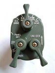
The next detail to take care of is the lettering for the courtesy light switch which will be an awesome finishing touch. I wanted to mimic nomenclature on the headlight switch for the instrument panel brightness settings and at the same time mimic the font that is on the intercom units so that everything matches.
Here is the lettering from my 3D model and here is the actual AM-1780 that shows the imprinted font I'm talking about...
VIC-1 PANEL WELD ASSY.JPG

Nos-Headlight-Switch-Control-Light-3-Lever-Military.jpg

20190210_142443.jpg

20190209_102830.jpg

Tha corbel font was the closest match to the intercom print I could find without spending days looking at fonts.
The 3 settings of the rotary switch will be OFF - DIM - PANEL BRT.
 
Last edited:

US6x4

Well-known member
Steel Soldiers Supporter
1,234
2,246
113
Location
Wenatchee, WA
Now I'm into the really fun stuff - detail lettering! The two options are to apply a decal or paint the lettering on. The decals seem cheesy and would probably not last as long as the painting option so I went to a graphics design place to have them cut out the words I wanted in vinyl with hopes of using the vinyl as a template. The places I went to told me it can't be done. They said vinyl can't be cut that small and if you paint over it the paint will leach behind the vinyl and run. I finally found a sign company that could cut vinyl letters in corbel font 3/16" tall and they did it free of charge! Now it's time to prove the graphics people wrong.

20190424_153852.jpg

20190424_171910.jpg

20190424_172959.jpg

20190424_173137.jpg

Using pin striping tape I laid out the locations for the descriptions based on where the handle of the 3-position switch would be pointed at each position and made sure everything was straight, level, and aligned. I used a tiny brush and 1 SHOT sign paint in flat white and gently painted in the letters. As the paint sat there it tended to pull itself out of the letters and onto the vinyl so I kept adding layers as that would happen until the paint thickness was about the same as the vinyl itself. There were many tricks to making this work; for one, you have to apply a lot of pressure to the vinyl to resist the paint from creeping under it, 2 - you can't pull the vinyl off too early or the paint will run, and 3 - you can't pull the vinyl off too late or it will dry to the vinyl and get pulled off with the template. I used my fingernail and then a round drinking glass to roll and press the vinyl down hard against the panel. I gently pulled off the vinyl templates after letting the paint sit for 1 hour and then let it cure for over 24 hours. I started with the OFF letters and once those turned out to my liking i resumed work on the others.

I didn't have templates for the lines that point to the letters from the handle so I made my own with the exacto knife again and some of the same vinyl the letters were cut from. In the back of my mind I thought I should leave well enough alone and not push my luck trying to add the lines thinking I might wreck the letters in the process but to me it just wasn't finished so after ignoring my precautionary friends I came back 2 days later and painted on the lines. This was a bit trickier since the lines wrap around the metal and the paint wanted to run just a little. Luckily this sign paint is thick and heavy.

After all the paint cured the panel is now ready to get wired up before the installation begins. This was a bit of a roll of the dice since I haven't done artsy stuff since college really, but I absolutely love the way it turned out!

20190428_175144.jpg

20190428_175358.jpg

20190428_175408.jpg

20190428_175416.jpg
 
Last edited:

US6x4

Well-known member
Steel Soldiers Supporter
1,234
2,246
113
Location
Wenatchee, WA
The wiring for the courtesy lights is basic and pretty simple to put together. I used all military connectors and wire (14 ga.), but the bulb receptacles used 16 ga. connectors.

20190402_181340.jpg

20190424_095340.jpg

20190427_072143.jpg


The wiring goes from the battery to the circuit breaker then to port A on the switch. Port B (taillight filament) goes to a wye splitter and port C (brakelight filament) goes to a wye splitter. After the splitter the wires go to each of the taillights. 3/4" automotive p-clamps hold the wye connectors with a shared bolt.

20190428_163831.jpg

20190428_163848.jpg
 
Last edited:

US6x4

Well-known member
Steel Soldiers Supporter
1,234
2,246
113
Location
Wenatchee, WA
On the passenger side of the panel the wire to the battery goes through a rubber grommet, out over the roof tube elbow, and the into a grommeted hole I drilled in the side cab support. Now the wire is hidden inside the tube and is heading straight for the batteries.

20190416_183446.jpg

20190416_183514.jpg

20190501_184156.jpg
 
Last edited:

US6x4

Well-known member
Steel Soldiers Supporter
1,234
2,246
113
Location
Wenatchee, WA
Getting closer to the finish line and some details before the soft top goes back on. I put some trim-loc rubber edging on all of the sheet metal edges that were not hemmed so that the top wouldn't get rubbed thru - it also gives the panel a nice finished look.

20190429_181143.jpg

20190429_181137.jpg

With the panel mounted & wired it's time to test out the courtesy lights...

20190428_195607.jpg

20190428_195618.jpg
 
Last edited:

US6x4

Well-known member
Steel Soldiers Supporter
1,234
2,246
113
Location
Wenatchee, WA
It's all starting to come together now that the intercom components are going on!

20190429_192020.jpg

20190430_201122.jpg

20190430_201140.jpg
 
Last edited:

US6x4

Well-known member
Steel Soldiers Supporter
1,234
2,246
113
Location
Wenatchee, WA
Here are the final installation photos with everything cleaned up and in place!

20190509_164345.jpg

20190509_164356.jpg

20190509_164428.jpg

20190509_164248.jpg

Driving around with an intercom makes cruises a pretty unique experience. It's nice to have the outside noise sealed out and be able to talk to passengers without yelling. I have been hooking up my ipod to have some background tunes but the sound level is pretty low and I need to figure out how to make the music louder. Having the 2-stage courtesy lights is awesome in the dark and makes those early hour startups much easier with the cabin flooded in red light and not needing flashlights to find things on the dash, floor or seats.
20220409_052932.jpg

20220409_052945.jpg


My next post will be a list of all the purchased parts I used to make this and more details about the intercom cables.

I hope some people find this write-up useful / inspiring to their future endeavors.
 
Last edited:
Top
AdBlock Detected

We get it, advertisements are annoying!

Sure, ad-blocking software does a great job at blocking ads, but it also blocks useful features of our website like our supporting vendors. Their ads help keep Steel Soldiers going. Please consider disabling your ad blockers for the site. Thanks!

I've Disabled AdBlock
No Thanks