• Steel Soldiers now has a few new forums, read more about it at: New Munitions Forums!

  • Microsoft MSN, Live, Hotmail, Outlook email users may not be receiving emails. We are working to resolve this issue. Please add support@steelsoldiers.com to your trusted contacts.

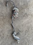
M1088A1 Spaghetti Monster

NDT

Well-known member
Steel Soldiers Supporter
10,441
6,491
113
Location
Camp Wood/LC, TX
What year model is it? If the bundles are cut, start looking for a parts truck. FMTVs are tricky to fix electrically even when the harnesses are still attached.
 

abfisher1798

Active member
189
87
28
Location
Blythe, California
2002.
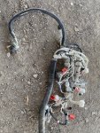
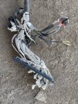
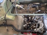
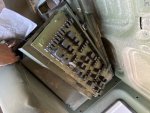
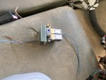
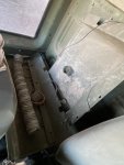
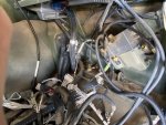
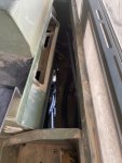
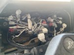
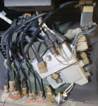
The harness looks intact, thankfully! No cut wires and all the connectors seem to be in place and appear to match with the truck harness.
Need to figure out how it goes in. I can't figure out how they even got it out without cutting anything.
 

NDT

Well-known member
Steel Soldiers Supporter
10,441
6,491
113
Location
Camp Wood/LC, TX
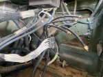
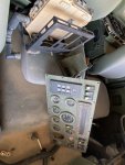
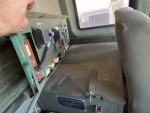
It goes behind the heater. Might help to remove it. Fan control solenoid is cannibalized, but your WTEC control is there thank goodness. Is your PDP in place?
 

abfisher1798

Active member
189
87
28
Location
Blythe, California
It goes behind the heater. Might help to remove it. Fan control solenoid is cannibalized, but your WTEC control is there thank goodness. Is your PDP in place?
From what I can tell, it looks like most of everything is here.
Running the harness behind the heater shouldn’t be too hard. I wasn’t sure if the wiper mechanism would share the space, but maybe so.
 

Attachments

B-Dog

Well-known member
164
288
63
Location
Denver, CO
From what I can tell, it looks like most of everything is here.
Running the harness behind the heater shouldn’t be too hard. I wasn’t sure if the wiper mechanism would share the space, but maybe so.

Ooof, I don't envy that mess, I'm also surprised that nothing was cut! I have a lot of my dash taken apart at the moment (M1083A0). Holler if you need pictures of anything in particular and I'd see what I can do.

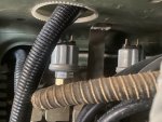
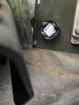
I'm pretty sure this is on the tractors only, it's a switch for the stop lights; where does this hose go? Does it go somewhere on the outside or is it vented to atmosphere? I'd venture to guess that's where the 2 lone yellow terminals go, pictured in your first post.

1620173533274.png
 

Suprman

Well-known member
Supporting Vendor
6,861
696
113
Location
Stratford/Connecticut
I believe it goes over to the hand brake valve to the right of the steer wheel. I have put that mess back together before. Its doable just take it slow.
 

abfisher1798

Active member
189
87
28
Location
Blythe, California
Ooof, I don't envy that mess, I'm also surprised that nothing was cut! I have a lot of my dash taken apart at the moment (M1083A0). Holler if you need pictures of anything in particular and I'd see what I can do.

I'm pretty sure this is on the tractors only, it's a switch for the stop lights; where does this hose go? Does it go somewhere on the outside or is it vented to atmosphere? I'd venture to guess that's where the 2 lone yellow terminals go, pictured in your first post.

View attachment 833569
I’d very much appreciate photos of the PDP connections, instrument panel connections and the aforementioned air lines.
Photos or a diagram that shows which connector is for which gauge will be helpful.
Photo of which wires connect to the air solenoid.
Any and all photos of the connections behind the dash for driver and passenger side.
 

Attachments

B-Dog

Well-known member
164
288
63
Location
Denver, CO
I need help connecting some small items on drivers side:
Start button
Brake light switch
Audible alarm
Air solenoids

Wires all have ID tags.

I don't have the starter switch or the buzzer handy but check schematic grids 123A and 110H, respectively.

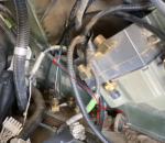
WK is the warning light, G is the gauge signal. You can make out the WK in the epicture below but be sure to look at your sensor(s). Look on sheet 21; grids 186F & 186G

1620343707814.png

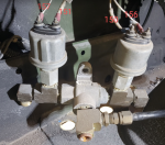
PX50 = Axle Lock
PX34 = Fan
In this picture, the supply is towards the camera (right angle fitting) and is connected to the fan solenoid. The axle lock solenoid is away from the camera.

1620344675035.png

Oops, reading>me. I just realized you were looking for the brake light switch. Are you referring the one in the picture above? If so, TL501 goes towards the front of the truck and is labeled, W2; TL502 is connected to the terminal closest to the camera.
 
Last edited:

abfisher1798

Active member
189
87
28
Location
Blythe, California
I don't have the starter switch or the buzzer handy but check schematic grids 123A and 110H, respectively.

WK is the warning light, G is the gauge signal. You can make out the WK in the epicture below but be sure to look at your sensor(s). Look on sheet 21; grids 186F & 186G

View attachment 833768

PX50 = Axle Lock
PX34 = Fan
In this picture, the supply is towards the camera (right angle fitting) and is connected to the fan solenoid. The axle lock solenoid is away from the camera.

View attachment 833769

Oops, reading>me. I just realized you were looking for the brake light switch. Are you referring the one in the picture above? If so, TL501 goes towards the front of the truck and is labeled, W2; TL502 is connected to the terminal closest to the camera.
Awesome! The photographs help big time.
 

B-Dog

Well-known member
164
288
63
Location
Denver, CO
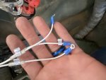
Here are a few more stray connectors. I can’t find their counterparts, maybe I’m missing another harness.

I don't say this at all trying to be condescending but have you seen sheets 2-5 in the schematic? There's a list of all the tags, plugs, receptacles, relays, CBs and their corresponding grids. (y)

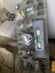
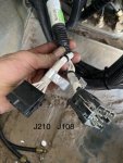
210 and what is likely 209, 209A or 209B is for the options panel. This is a separate harness for the 8-ish(?) optional switches and tach that bolt on top of the heater.

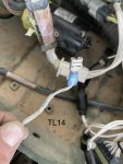
TL14 - rotary beacon ground. This should plug into that long black block, shown as "TB2" all over the place. It doesn't really matter which terminal but if you want to put it back where it shows on the schematic, terminal 12. See Sheet 16, F141.

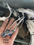
PX50 - Axle lock - plugs into the solenoid that I had a picture of, above.
The other ones in your hand, assuming they're the same as what I have;
P34 - Fan solenoid
P99 - chemical alarm
P65 - Rotary beacon connector

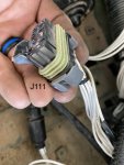
J111 - CTIS Control unit. This plugs into P111 which is part of the harness that connects the Control Unit (buttons) to the controller under the passenger dash. You may or may not have the harness(?)
 

abfisher1798

Active member
189
87
28
Location
Blythe, California
I don't say this at all trying to be condescending but have you seen sheets 2-5 in the schematic? There's a list of all the tags, plugs, receptacles, relays, CBs and their corresponding grids. (y)

210 and what is likely 209, 209A or 209B is for the options panel. This is a separate harness for the 8-ish(?) optional switches and tach that bolt on top of the heater.

TL14 - rotary beacon ground. This should plug into that long black block, shown as "TB2" all over the place. It doesn't really matter which terminal but if you want to put it back where it shows on the schematic, terminal 12. See Sheet 16, F141.

PX50 - Axle lock - plugs into the solenoid that I had a picture of, above.
The other ones in your hand, assuming they're the same as what I have;
P34 - Fan solenoid
P99 - chemical alarm
P65 - Rotary beacon connector

J111 - CTIS Control unit. This plugs into P111 which is part of the harness that connects the Control Unit (buttons) to the controller under the passenger dash. You may or may not have the harness(?)
Yes, I have those schematics. I can ID what most of the connections are supposed to be. I may know what they are, but that doesn't tell me where they go. Like I know P99 is for chemical alarm, but I do not know what that is or where the wiring would be located, though I'm not too worried about that one.
I figured most of them out, with help from the pictures you shared.

What concerns me more is the CTIS wire harness is missing, though I am pretty sure that can be addressed later.

My fan/diff lock solenoid wires were cut and the tags and connectors are long gone, which is what initially threw me off the trail. I can make new connectors, just need to figure out which solenoid is for which air line.

Overall, this is coming along well, thanks in large part to your help. I am about ready to connect the batteries and then, see what happens.
 

B-Dog

Well-known member
164
288
63
Location
Denver, CO
Yes, I have those schematics. I can ID what most of the connections are supposed to be. I may know what they are, but that doesn't tell me where they go. Like I know P99 is for chemical alarm, but I do not know what that is or where the wiring would be located, though I'm not too worried about that one.
I figured most of them out, with help from the pictures you shared.

What concerns me more is the CTIS wire harness is missing, though I am pretty sure that can be addressed later.

My fan/diff lock solenoid wires were cut and the tags and connectors are long gone, which is what initially threw me off the trail. I can make new connectors, just need to figure out which solenoid is for which air line.

Overall, this is coming along well, thanks in large part to your help. I am about ready to connect the batteries and then, see what happens.
Nice, glad it's all coming together and that makes sense about not knowing where things go. I'm not sure about P99 either.
My CTIS harness is missing as well. Post up if you find a source for a new one!
 
Top
AdBlock Detected

We get it, advertisements are annoying!

Sure, ad-blocking software does a great job at blocking ads, but it also blocks useful features of our website like our supporting vendors. Their ads help keep Steel Soldiers going. Please consider disabling your ad blockers for the site. Thanks!

I've Disabled AdBlock
No Thanks