• Steel Soldiers now has a few new forums, read more about it at: New Munitions Forums!

  • Microsoft MSN, Live, Hotmail, Outlook email users may not be receiving emails. We are working to resolve this issue. Please add support@steelsoldiers.com to your trusted contacts.

1996 M1097A2 Self induced charging issue

DFink

New member
11
2
1
Location
Roanoke, Virginia
Quick back story.... Moving the batteries under the hood, they are still sitting/ hooked up in the passenger side. Military dash mount has been removed. Gauges, run/start switch, lights switch all are hanging loose. Started the truck the other day and the charger is maxed out. I know I either have a short or a wire not connected.
I am trying to figure out the FIELD and SENSE wire. Thanks for the help!!!
 

TOBASH

Father, Surgeon, Cantankerous Grouch
Steel Soldiers Supporter
Supporting Vendor
3,754
3,824
113
Location
Brooklyn, NY
TMs are free and contain wiring diagrams.
They are located above in the stickies AND on the main Steel Soldiers index page in a TM section.
 

Retiredwarhorses

Well-known member
Steel Soldiers Supporter
4,501
4,395
113
Location
Brentwood, Calif
Quick back story.... Moving the batteries under the hood, they are still sitting/ hooked up in the passenger side. Military dash mount has been removed. Gauges, run/start switch, lights switch all are hanging loose. Started the truck the other day and the charger is maxed out. I know I either have a short or a wire not connected.
I am trying to figure out the FIELD and SENSE wire. Thanks for the help!!!
if a gauge is maxed out, you have a wire disconnected, the voltage gauge only has 2 wires, 24v and ground, use a multimeter
to determine your true alternator output.
 

DFink

New member
11
2
1
Location
Roanoke, Virginia
Finally, I have a chance today to check some voltages.

Key on engine not running
+14 V 13.5vdc
AC 0vdc
Ign 24.5vdc

Engine running
14 V 17vdc
AC 13vdc
Ign 32vdc

I've went through the wiring and haven't found anything obvious yet. Tested the alternator and regulator with the Niehoff PDF and it looks like everything is okay.
 

Retiredwarhorses

Well-known member
Steel Soldiers Supporter
4,501
4,395
113
Location
Brentwood, Calif
Finally, I have a chance today to check some voltages.

Key on engine not running
+14 V 13.5vdc
AC 0vdc
Ign 24.5vdc

Engine running
14 V 17vdc
AC 13vdc
Ign 32vdc

I've went through the wiring and haven't found anything obvious yet. Tested the alternator and regulator with the Niehoff PDF and it looks like everything is okay.
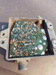
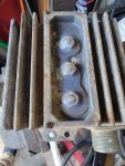
32vdc on the IGN? You have a bad regulator
17vdc on the 14v Tap? Bad regulator
AC is a signal….not voltage.

what is the running battery voltage? I would venture to guess 32vdc, same as IGN…. bad regulator.
 
Top