• Steel Soldiers now has a few new forums, read more about it at: New Munitions Forums!

  • Microsoft MSN, Live, Hotmail, Outlook email users may not be receiving emails. We are working to resolve this issue. Please add support@steelsoldiers.com to your trusted contacts.

Another LMTV Alternator Gremlin Identified - Battery BT2(-) Connection

sarge351

New member
29
2
1
Location
Allen, Texas
I finally tracked down the source of my Alternator problems. I owe a big "Thank You!" to Suprman for his help. I appreciate all his input and help on this forum, and in the world.

When I took possession of my truck at Fort Hood last summer, it would fire right up and run, but the alternator would not charge. On startup, the Voltmeter would go up to the Green (24-28V) for a few seconds, then it would drop down to 14V. The Voltage Regulator would alternate flashing both the 14 V and 28 V LED in red.

After ruling out the Alternator (tested by a Niehoff service shop), checking the Energizing Circuit, doing the Suprman trick of Substituting another 24V signal from the Fuel Governor Solenoid, and trying a known functional Voltage Regulator, my mechanic and I were at a loss.

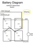
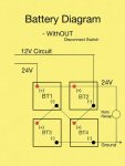
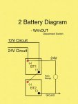
The FMTV's have 2 different kinds of Battery Interconnects, With and WithOUT the Disconnect Switch. My truck has the WithOUT. We were mislead by the diagram, which does not clearly illustrate the 12VDC Circuit connection to the BT2 (-) terminal.

Once we replaced this missing connection (my 12 Volt interconnect cables were missing components on purchase), all my problems cleared up. The Voltmeter runs in the green, and my alternator is charging. Additionally, my CTIS system was not functional, and the controller was disconnected, because it kept alarming. After replacing the missing connection, my CTIS is now working. Bonus!!

I did a revised battery diagram to illustrate what we missed on my OEM diagram:


coachgeo

Well-known member
5,134
3,455
113
Location
North of Cincy OH
I finally tracked down the source of my Alternator problems. I owe a big "Thank You!" to Suprman for his help. I appreciate all his input and help on this forum, and in the world.

When I took possession of my truck at Fort Hood last summer, it would fire right up and run, but the alternator would not charge. On startup, the Voltmeter would go up to the Green (24-28V) for a few seconds, then it would drop down to 14V. The Voltage Regulator would alternate flashing both the 14 V and 28 V LED in red.

After ruling out the Alternator (tested by a Niehoff service shop), checking the Energizing Circuit, doing the Suprman trick of Substituting another 24V signal from the Fuel Governor Solenoid, and trying a known functional Voltage Regulator, my mechanic and I were at a loss.

The FMTV's have 2 different kinds of Battery Interconnects, With and WithOUT the Disconnect Switch. My truck has the WithOUT. We were mislead by the diagram, which does not clearly illustrate the 12VDC Circuit connection to the BT2 (-) terminal.

Once we replaced this missing connection (my 12 Volt interconnect cables were missing components on purchase), all my problems cleared up. The Voltmeter runs in the green, and my alternator is charging. Additionally, my CTIS system was not functional, and the controller was disconnected, because it kept alarming. After replacing the missing connection, my CTIS is now working. Bonus!!

I did a revised battery diagram to illustrate what we missed on my OEM diagram:

PLEASE UPLOAD PICS. This post will become useless information in a very short time with out uploading them
 

sarge351

New member
29
2
1
Location
Allen, Texas
PLEASE UPLOAD PICS. This post will become useless information in a very short time with out uploading them
Please educate me on how to post with the forum. I am using Tapatalk app on an Ipad. I did upload the pics from my device. Do I need to upload from a PC instead?


Sent from my iPad using Tapatalk
 

sarge351

New member
29
2
1
Location
Allen, Texas
Please educate me on how to post with the forum. I am using Tapatalk app on an Ipad. I did upload the pics from my device. Do I need to upload from a PC instead?


Sent from my iPad using Tapatalk
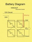
Another more OEM versionIMG_0341.jpg


Uploaded using 2 different interface options. Let me know if this does or does not upload pic.


Sent from my iPad using Tapatalk
 

coachgeo

Well-known member
5,134
3,455
113
Location
North of Cincy OH
for clarity... and for archiving....

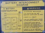
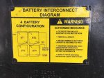
. Clarity.... the updated drawings for A0 above.... no one has mentioned if this is correct or not and why..... or is it just another way to go about it... and either one works. I do see that drawing does not show well the ground to chassis as good as the OEM battery A0 diagram plate archived below.
. Archiving:

A1 image into this thread
b0e7c8de4832526bc019031e23590e62.jpg

A0 image
11e6e82ebce87ca020cc01079be7f6d3.jpg
 
Last edited:

Awesomeness

Well-known member
Steel Soldiers Supporter
1,813
1,518
113
Location
Orlando, FL
What he has drawn is not actually different, he just misunderstood the original diagram. The original A0 diagram shows the 12V wire coming off in the center right of the diagram, pointing to the letters "12V". The diagram correctly shows 3 wires leaving the batteries (GND, 12V, 24V). So it is correct, too.

But if this helps clarify the diagram for others, fantastic.
 

coachgeo

Well-known member
5,134
3,455
113
Location
North of Cincy OH
What he has drawn is not actually different, he just misunderstood the original diagram. The original A0 diagram shows the 12V wire coming off in the center right of the diagram, pointing to the letters "12V". The diagram correctly shows 3 wires leaving the batteries (GND, 12V, 24V). So it is correct, too.

But if this helps clarify the diagram for others, fantastic.
good points. the drawing does not show ground to chassis? like the OEM one does though.
 

scottmandu

Active member
822
36
28
Location
Texas
Not all A1's have the battery disconnect solenoids. That appears to be a running change in the 2003 model year. Older A1's have the same battery wiring as the A0.
 

coachgeo

Well-known member
5,134
3,455
113
Location
North of Cincy OH
did the 1079's have 12 or 24v bank feed into the box? Or a seperate bank? If so curious to the design of the setup. If someone has a suggested starting point in the TM's will happily take a look myself.
 

coachgeo

Well-known member
5,134
3,455
113
Location
North of Cincy OH
Last edited:

Ronmar

Well-known member
3,813
7,403
113
Location
Port angeles wa
did the 1079's have 12 or 24v bank feed into the box? Or a seperate bank? If so curious to the design of the setup. If someone has a suggested starting point in the TM's will happily take a look myself.
Playing around in the schematics I came across 2 van schematics. You can find them in: TM 9-2320-365-20-1 sheet 31-32 of 34(page 1650 ish). One is DC the other is AC power distrubution for the van. Looks like it gets 24V from the chassis for DC lights and fans. No indication of “house” batteries for the 1079 van...
 

Ronmar

Well-known member
3,813
7,403
113
Location
Port angeles wa
all good but what number /tag on the 12v? got same problem, got 4 wires coming into battery compartment. So out of the four what is the 12v.
Like I said in the other post, you are going to have to trace the wires to be sure which is which. This is an area you need to be absolutely sure it’s right as you can do soe serious arc welding with the batteries and leads involved:)
 

Goodpedro

New member
16
1
3
Location
Canada
ok guys, i also have 4 wires coming in the battery compartment from cab. i also have no 12 volt cause i too have what looks like a missing wire to complete the 12 v circuit. So two short wires have tags (tl 39 and tl 10). Both are attached to Bt1 positive (24V) so far so good. Now the 2 remainig wires are TL 99 and TL48. Of course got a red wire that connects both BT1 and BT2 positive. now comes the strange part. TL 99 comes from the cab and it s also hooked to BT 2 positive??? In the electrical shematic it says that TL 99 is attached to BT 2neg, not positive. It would make sense since it could very well be my missing wire to complete the 12 v circuit??? Also, the 4th wire to come from the cab is tagged TL 48.....in my case it is hooked to a home made kill switch (to the to screw kill position) Again the shematic says it should be attached to BT4 Negative. So can anybody confirm this, mainly that TL 99 shoulb be on BT 2 Negative and not on BT 2 positive. I am very much afraid to creat an electrical arc and screw everything up. To recap truck starts very well with full charged batteries. But if i hit the higway beams, the batteries drain very fast. At first il looks like the alternator or regulator were the culprits until my buddy noticed that my 12v circuit was leading nowhere. The zigzag wire is good, it ends at Bt2 negative just like the yellow diagram under the batterie box.... but from BT2 neg nothing is hooked to go to the cab. So it may be TL 99 that should be attached there, not on BT2 positive. Help
So only BT1 and BT2 batteries loose their voltage when i turn on the lights. Make sense since the 12v part is never sollicitated since the circuit is not hooked to anything. Bt3 and BT4 stay full charge
 
Top
AdBlock Detected

We get it, advertisements are annoying!

Sure, ad-blocking software does a great job at blocking ads, but it also blocks useful features of our website like our supporting vendors. Their ads help keep Steel Soldiers going. Please consider disabling your ad blockers for the site. Thanks!

I've Disabled AdBlock
No Thanks