• Steel Soldiers now has a few new forums, read more about it at: New Munitions Forums!

  • Microsoft MSN, Live, Hotmail, Outlook email users may not be receiving emails. We are working to resolve this issue. Please add support@steelsoldiers.com to your trusted contacts.

Another MEP 006a/105a love hate relationship!

Sentinel 9

New member
9
15
3
Location
Florida, USA
Good morning all.
Has anyone successfully used an aftermarket AVR (auto voltage regulator) on an MEP 006A? I am done with the old regulator exciter box issues.
Someone told me they used a basler avc 63 -4 but its only firing up 2 of the 3 legs.
If this has been answered or addressed before, please point me in the right direction. Thank you all.
9
 

Sentinel 9

New member
9
15
3
Location
Florida, USA
There is no power on 1 of the 3 phases. Top lug. The avr sense lines a connected to the other two legs and they are generating power. I assumed because the avr is meant for single phase, it will only produce power on two phases only and not the 3.
 

Scoobyshep

Well-known member
1,216
1,736
113
Location
Florida
That's not how it works.

In general, an Ave only needs to see voltage and it regulates the voltage by adjusting the magnetic field. The windings all see the same field and create voltage. Where are you metering it? There may be a bad connection between the head and that point or you have a bad winding, or someone changed how the head is tapped.

Sent from my SM-S908U using Tapatalk
 

Sentinel 9

New member
9
15
3
Location
Florida, USA
That's not how it works.

In general, an Ave only needs to see voltage and it regulates the voltage by adjusting the magnetic field. The windings all see the same field and create voltage. Where are you metering it? There may be a bad connection between the head and that point or you have a bad winding, or someone changed how the head is tapped.

Sent from my SM-S908U using Tapatalk
1 How can i check to see if the winding is faulty?
2 are there diodes in those 006as that can go faulty and cause the winding not to produce power?
 

Scoobyshep

Well-known member
1,216
1,736
113
Location
Florida
There are diodes but they are on the rotor, their failure would not cause a loss of 1 leg.

Check it at the voltage reconnecton board. Let me know what you have between the following:
T1 to T2
T2 to T3
T3 to T1
T1 to T12
T2 to T12
T3 to T12

I assume you have a multi meter and are comfortable using it?

Sent from my SM-S908U using Tapatalk
 

Sentinel 9

New member
9
15
3
Location
Florida, USA
There are diodes but they are on the rotor, their failure would not cause a loss of 1 leg.

Check it at the voltage reconnecton board. Let me know what you have between the following:
T1 to T2
T2 to T3
T3 to T1
T1 to T12
T2 to T12
T3 to T12

I assume you have a multi meter and are comfortable using it?

Sent from my SM-S908U using Tapatalk
What i am checking for voltage with unit running. Or continuity resistance with unit not running.?
 

Sentinel 9

New member
9
15
3
Location
Florida, USA
There are diodes but they are on the rotor, their failure would not cause a loss of 1 leg.

Check it at the voltage reconnecton board. Let me know what you have between the following:
T1 to T2
T2 to T3
T3 to T1
T1 to T12
T2 to T12
T3 to T12

I assume you have a multi meter and are comfortable using it?

Sent from my SM-S908U using Tapatalk
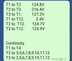
I did the test. Results as follows:
T1. To T2. 124.8 volts
T2 to t3. 216.4 volts
T3 to t1. 127.2 volts
T1 to t12. 2.4 volts
T2 to t12. 124.7 volts
T3 to t12 124.9 volts

Continuity. T1 to t4 only
T2 to T 3,5,6,7,8,9,10,11,12
T3 to T 2,5,6,7,8,9,10,11,12.
I just want to say, i truly appreciate your input in this matter.
 

Sentinel 9

New member
9
15
3
Location
Florida, USA
There are diodes but they are on the rotor, their failure would not cause a loss of 1 leg.

Check it at the voltage reconnecton board. Let me know what you have between the following:
T1 to T2
T2 to T3
T3 to T1
T1 to T12
T2 to T12
T3 to T12

I assume you have a multi meter and are comfortable using it?

Sent from my SM-S908U using Tapatalk
 

Attachments

Scoobyshep

Well-known member
1,216
1,736
113
Location
Florida
Something is open. Since the reconnecting board is where the head gets terminated, it's either on the back side of the board or in the head. Check the wiring from the head (look for 12 large wires). Follow them from the head to the board. Check for damage for a bad connection on the board.
 

Sentinel 9

New member
9
15
3
Location
Florida, USA
Something is open. Since the reconnecting board is where the head gets terminated, it's either on the back side of the board or in the head. Check the wiring from the head (look for 12 large wires). Follow them from the head to the board. Check for damage for a bad connection on the board.
Problem solved.

I mapped out the windings (draw label according to parallel star.) Started testing each winding. All windings checked out. Then proceeded to continuity test the connection between the windings.
3 terminal on the voltage config board was corroded and 1 of the 3 was loose. Cleaned, new lock nuts and fired it up. The old bird came to life on all legs. Thank you Scoobyshep
 

Scoobyshep

Well-known member
1,216
1,736
113
Location
Florida
Problem solved.

I mapped out the windings (draw label according to parallel star.) Started testing each winding. All windings checked out. Then proceeded to continuity test the connection between the windings.
3 terminal on the voltage config board was corroded and 1 of the 3 was loose. Cleaned, new lock nuts and fired it up. The old bird came to life on all legs. Thank you Scoobyshep
Glad it was something simple. Happy to help
 
Top
AdBlock Detected

We get it, advertisements are annoying!

Sure, ad-blocking software does a great job at blocking ads, but it also blocks useful features of our website like our supporting vendors. Their ads help keep Steel Soldiers going. Please consider disabling your ad blockers for the site. Thanks!

I've Disabled AdBlock
No Thanks