MarcusOReallyus
Well-known member
- 4,524
- 816
- 113
- Location
- Virginia
Someone was asking recently about bypassing the BO light switch, and I could not find a good how-to on it. Since I did it on my truck today, I decided to take some pics and write it up.
Tinstar and cucvrus, please avert your eyes. Non-standard mayhem is about to begin.
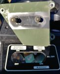
The first thing I did was to remove the dash panel, then drill out the three rivets holding the BO switch panel. Dunno why they needed to be riveted in place!
With the panel removed, I unplugged the two switches. No worries about getting the plugs mixed up - they are different. On my truck, the right switch is the master switch with three positions. Top to bottom they are: Service lights, ALL OFF, and Blackout.

The left switch is a momentary OFF switch for the BO lights. There is no need to do anything with this switch. Remove it or leave it in place, plugged in. It doesn't matter.
With the switch plate removed, I then used my meter to determine the function of the master switch. There are two columns of three contacts each, as seen here:

The left column is electrically isolated from the right column. They are never connected no matter the position of the switch.
In the diagram below, I used red lines to show where there is continuity for each of the three switch positions:

As you can see, when the master switch is in the middle position, nothing is connected. No lights will work. Nada.
When the switch is in the top position (Service Lights ON), the bottom rows are connected to the middle rows. Remember, there's no connection between columns, only between rows within a column.
When the switch is in the bottom position (Blackout Lights ON), the top row is connected to the middle row.
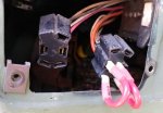
So, where does that leave us? Howzaboutdat? This is actually very simple! In order to have the service (civilian) lights working all the time, all we need to do is to connect the middle row with the lower row. Since the connectors on the backs of the switches are standard .250" tabs, we can just make up some short jumpers using some wire and some male .250 connectors. I decided to use some 10 gauge I had handy, to make sure that my jumpers would not be causing any voltage drop in my lighting circuits. 14 gauge is probably enough, though.
So, here's what the jumpers look like in place:

Lastly, I threw some electrical tape on it just to make sure that nothing will vibrate out of position.

Tuck everything up and tie wrap things in place so they don't dangle, put the switch plate back in place, and we're done. (Well, I did sneak in another mod. I put a momentary ON in place of the left switch for a manual GP backup. The hole is already there, and it's a standard size, so....
The end result is that your service lights (the regular civilian lights; headlights, tailights, turn signals, brakes, all that stuff) will operate normally as if there were no BO light system. Your BO lights will not turn on at all. Both the right and left switch are non-functional.
That's all there is to it. Two jumpers. Everything works fine, and if I ever repent of my sin in modifying The Sacred Design, I can just pull the jumpers out and put everything back like it was. No cutting, no splicing, no monkeying with the stock wiring.
I hope this is useful to someone!
Tinstar and cucvrus, please avert your eyes. Non-standard mayhem is about to begin.
The first thing I did was to remove the dash panel, then drill out the three rivets holding the BO switch panel. Dunno why they needed to be riveted in place!
With the panel removed, I unplugged the two switches. No worries about getting the plugs mixed up - they are different. On my truck, the right switch is the master switch with three positions. Top to bottom they are: Service lights, ALL OFF, and Blackout.

The left switch is a momentary OFF switch for the BO lights. There is no need to do anything with this switch. Remove it or leave it in place, plugged in. It doesn't matter.
With the switch plate removed, I then used my meter to determine the function of the master switch. There are two columns of three contacts each, as seen here:

The left column is electrically isolated from the right column. They are never connected no matter the position of the switch.
In the diagram below, I used red lines to show where there is continuity for each of the three switch positions:

As you can see, when the master switch is in the middle position, nothing is connected. No lights will work. Nada.
When the switch is in the top position (Service Lights ON), the bottom rows are connected to the middle rows. Remember, there's no connection between columns, only between rows within a column.
When the switch is in the bottom position (Blackout Lights ON), the top row is connected to the middle row.
So, where does that leave us? Howzaboutdat? This is actually very simple! In order to have the service (civilian) lights working all the time, all we need to do is to connect the middle row with the lower row. Since the connectors on the backs of the switches are standard .250" tabs, we can just make up some short jumpers using some wire and some male .250 connectors. I decided to use some 10 gauge I had handy, to make sure that my jumpers would not be causing any voltage drop in my lighting circuits. 14 gauge is probably enough, though.
So, here's what the jumpers look like in place:

Lastly, I threw some electrical tape on it just to make sure that nothing will vibrate out of position.

Tuck everything up and tie wrap things in place so they don't dangle, put the switch plate back in place, and we're done. (Well, I did sneak in another mod. I put a momentary ON in place of the left switch for a manual GP backup. The hole is already there, and it's a standard size, so....
The end result is that your service lights (the regular civilian lights; headlights, tailights, turn signals, brakes, all that stuff) will operate normally as if there were no BO light system. Your BO lights will not turn on at all. Both the right and left switch are non-functional.
That's all there is to it. Two jumpers. Everything works fine, and if I ever repent of my sin in modifying The Sacred Design, I can just pull the jumpers out and put everything back like it was. No cutting, no splicing, no monkeying with the stock wiring.
I hope this is useful to someone!

Last edited:


