- 2,096
- 646
- 113
- Location
- Orlando, FL
On the way to the Georgia Rally this year my driver side alternator started over charging. I stopped to check it and at idle the charge was normal but the voltage increased as the rpms did getting to 17+ volts. After checking connections I disconnected the B+ wire off the back of the alternator and continued the trip.
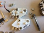
After getting home I pulled the alternator off and took it apart. I ordered replacement parts and did a partial rebuild of the alternator. Since the brushes had very little wear I elected not to replace the bearings.
Rebuilding alternators is easy and usually straight forward. This series of GM alternators are easier than many because all the internal connections use fasteners.
The process is as follows:
Remove the 4 case bolts. The rear end casting should pull off with the stator, use a screw driver to loosen the stator from the front casting if necessary. Remove the 3 nuts that attach the stator leads to the rectifier and with a screw driver loosen the stator from the end casting and set it aside.
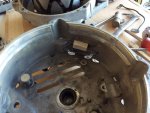
As you remove the internal components make note of the insulators on the B+ bolt and relay terminal bolt next to it. The 4 8/32 screws that attach the regulator/brush holder assembly and one side of the rectifier have insulating sleeves on the shoulder, Make sure these aren’t damaged. There is an insulator between the rectifier negative heat sink and end casting on the opposite side from the B- bolt. There is an insulating sleeve on the B- bolt that goes between the rectifier negative heat sink and through the end casting. Check these are there and in good condition.
If you elect to replace the bearings, be sure you support the casting near the bearing as you press them out and in so you don’t break the casting.
Assembly is the easy, just be sure the insulators go back where they should.
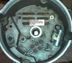
The B- bolt will be a little snug going into the negative heat sink slot. Just tap it in and be sure the insulator is on the bolt as shown.
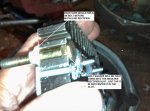
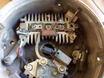
Install the rectifier and lightly snug the 8/32 screw and nut on the B- bolt. Note the wire going under the 8/32 screw. Check to make sure the B- bolt is square with the negative heat sink. You may have to remove the rectifier and tap the bolt sideways to get it to line up correctly with the through hole in the end casting so you don’t cut the insulator when you tighten it down.

Place the foam dust shield over the regulator terminals and place the brush holder on the regulator. The heat sink on the regulator goes against the end casting. The brush retaining pin goes through a hole in the back of the end casting and is removed after the alternator is completely assembled.
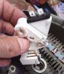
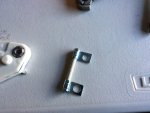
Place the trio over the rectifier terminals and install the relay terminal bolt with insulators and terminal. Attach the resistor, trio terminal, and wire terminal to the regulator as shown. Be careful installing the 3 regulator/brush holder screws so the insulators are not damaged. Install the B+ bolt with insulators, terminal, and self tapping screw into the positive heat sink. Attach capacitor terminal to the positive heat sink using a self tapping screw.
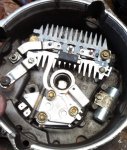
Recheck all of the fasteners and make sure all are tight. Install the stator lining up the 3 stator leads with the rectifier terminals and the slots on the outside of the stator with the end casting then tap into the end casting. Install the 3 nuts on the rectifier terminals and tighten. Check the 3 stator leads are not touching the negative heat sink.
Carefully place the end casting assembly over the front casting and rotor assembly so the rotor goes into the end casting bearing. There is a alignment pin on the end casting that goes into a hole on the front casting. Once everything is together, install the 4 case bolts and snug lightly. Spin the pulley to make sure nothing is binding or rubbing. If all is good, tighten the case bolts and pull the brush retaining pin.
Install the alternator in the vehicle, check operation, and you are done.
After getting home I pulled the alternator off and took it apart. I ordered replacement parts and did a partial rebuild of the alternator. Since the brushes had very little wear I elected not to replace the bearings.
Rebuilding alternators is easy and usually straight forward. This series of GM alternators are easier than many because all the internal connections use fasteners.
The process is as follows:
Remove the 4 case bolts. The rear end casting should pull off with the stator, use a screw driver to loosen the stator from the front casting if necessary. Remove the 3 nuts that attach the stator leads to the rectifier and with a screw driver loosen the stator from the end casting and set it aside.
As you remove the internal components make note of the insulators on the B+ bolt and relay terminal bolt next to it. The 4 8/32 screws that attach the regulator/brush holder assembly and one side of the rectifier have insulating sleeves on the shoulder, Make sure these aren’t damaged. There is an insulator between the rectifier negative heat sink and end casting on the opposite side from the B- bolt. There is an insulating sleeve on the B- bolt that goes between the rectifier negative heat sink and through the end casting. Check these are there and in good condition.
If you elect to replace the bearings, be sure you support the casting near the bearing as you press them out and in so you don’t break the casting.
Assembly is the easy, just be sure the insulators go back where they should.

The B- bolt will be a little snug going into the negative heat sink slot. Just tap it in and be sure the insulator is on the bolt as shown.

Install the rectifier and lightly snug the 8/32 screw and nut on the B- bolt. Note the wire going under the 8/32 screw. Check to make sure the B- bolt is square with the negative heat sink. You may have to remove the rectifier and tap the bolt sideways to get it to line up correctly with the through hole in the end casting so you don’t cut the insulator when you tighten it down.

Place the foam dust shield over the regulator terminals and place the brush holder on the regulator. The heat sink on the regulator goes against the end casting. The brush retaining pin goes through a hole in the back of the end casting and is removed after the alternator is completely assembled.

Place the trio over the rectifier terminals and install the relay terminal bolt with insulators and terminal. Attach the resistor, trio terminal, and wire terminal to the regulator as shown. Be careful installing the 3 regulator/brush holder screws so the insulators are not damaged. Install the B+ bolt with insulators, terminal, and self tapping screw into the positive heat sink. Attach capacitor terminal to the positive heat sink using a self tapping screw.

Recheck all of the fasteners and make sure all are tight. Install the stator lining up the 3 stator leads with the rectifier terminals and the slots on the outside of the stator with the end casting then tap into the end casting. Install the 3 nuts on the rectifier terminals and tighten. Check the 3 stator leads are not touching the negative heat sink.
Carefully place the end casting assembly over the front casting and rotor assembly so the rotor goes into the end casting bearing. There is a alignment pin on the end casting that goes into a hole on the front casting. Once everything is together, install the 4 case bolts and snug lightly. Spin the pulley to make sure nothing is binding or rubbing. If all is good, tighten the case bolts and pull the brush retaining pin.
Install the alternator in the vehicle, check operation, and you are done.
Last edited:


