• Steel Soldiers now has a few new forums, read more about it at: New Munitions Forums!

  • Microsoft MSN, Live, Hotmail, Outlook email users may not be receiving emails. We are working to resolve this issue. Please add support@steelsoldiers.com to your trusted contacts.

Custom winch wiring.

luckypjs20

New member
12
5
3
Location
Cleburne tx
I have an A0 winch with the harness from that.

I am installing on an A1 truck. Instead of wiring into my truck harnesses, I am proposing rewiring it to be always hot. I took a crack at the wiring schematic.

Will post next post the pictures.

@Ronmar any thoughts? Anyone else?


Sent from my iPhone using Tapatalk
I was looking at wiring in a wireless remote to mine I think it would be useful for pulling other things around
 

Guruman

Not so new member
Steel Soldiers Supporter

ramdough

Well-known member
1,554
1,729
113
Location
Austin, Texas
1699214010336.png

at P913, I had disconnected pins 7, 8, and 15. So I am thinking I need to run a wire from 15 to the PDP P309 then cut the wires and splice my new wire to both pins 1 and 2. That should hot wire my PTO to my switches.

half of me is thinking of just reinserting those pins and leaving it stock. Thoughts?
 

ramdough

Well-known member
1,554
1,729
113
Location
Austin, Texas
View attachment 909801

at P913, I had disconnected pins 7, 8, and 15. So I am thinking I need to run a wire from 15 to the PDP P309 then cut the wires and splice my new wire to both pins 1 and 2. That should hot wire my PTO to my switches.

half of me is thinking of just reinserting those pins and leaving it stock. Thoughts?
Ok,

Refreshed my memory…. I already ran 1904 from the dash area to my kick panel, so I am proceeding with doing the alternate wiring.

I also noticed I used 16 gauge wire for the 1904 run from the dash. That wire was supposed to hit p309-1 and p309-2. Looking at the above wiring diagram, there is a 15a fuse feeding 1904. So, I might have undersized the wire a little for the solenoid draw.

New thought is to:
1. Disconnect 1904A at P309-1
2. Direct feed pin P309-1 from P309-3 using sufficient wire gauge for 15a….. at least 14 awg.
3. Connect P309-2 to my from dash 1904.

Side effect, k42 relay would be unused and the transmission would not know the PTO was engaged.

@Ronmar or anyone else have an opinion?


Sent from my iPhone using Tapatalk
 
Last edited:

Wingnut13

Well-known member
235
562
93
Location
Strafford, NH
Errr, From what I recall reading about the transmission…. When the PTO is engaged the trans controller locks up the converter clutch to cut the converter to eliminate slipping and heating the trans.
 

ramdough

Well-known member
1,554
1,729
113
Location
Austin, Texas
Errr, From what I recall reading about the transmission…. When the PTO is engaged the trans controller locks up the converter clutch to cut the converter to eliminate slipping and heating the trans.
If that is the case, then I need to return the wiring back to stock. I should be able to do that.

Can anyone confirm how that works?


Sent from my iPhone using Tapatalk
 

ramdough

Well-known member
1,554
1,729
113
Location
Austin, Texas
@Ronmar and I had a good long discussion and the conclusion was that the PTO is powered off of the same drive gear as the scavenge pump for the transfer case which is powered from the carrier of the torque converter so it has power at all times the engine is running.


Sent from my iPhone using Tapatalk
 

Ronmar

Well-known member
3,845
7,474
113
Location
Port angeles wa
@Ronmar and I had a good long discussion and the conclusion was that the PTO is powered off of the same drive gear as the scavenge pump for the transfer case which is powered from the carrier of the torque converter so it has power at all times the engine is running.


Sent from my iPhone using Tapatalk
That is correct, the lockup clutch is only engaged in 3rd gear and above(truck in motion), and it stays engaged 100% of the time untill the trans shifts to 2nd.

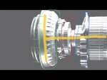
here is the input end of the Allison,3000 series, minus the housing.

It shows the input flex plates and the input flange on the left, which is connected to and spins the TC housing(green). Those bumps on the housing are what the transmission input RPM sensor(lower right front on trans housing), senses as they spin by at engine RPM. The TC housing connects to a hollow output shaft, which drives the accessory/PTO drive gear(red) and passes into the hydraulic pump(blue), all driven at engine RPM. The TC turbine is inside the TC pump/housing as is the lockup clutch, and drives the turbine output shaft(yellow) hydraulically, or hard coupled by lockup, thru that hollow TC housing/shaft. It spins the first carrier, and the Turbine RPM sensor on top of the control module senses the mid section/turbine RPM of the spinning section shown to the right in this pic.


IMG_3792.jpeg
 
Last edited:

ramdough

Well-known member
1,554
1,729
113
Location
Austin, Texas
That is correct, the lockup clutch is only engaged in 3rd gear and above(truck in motion), and it stays engaged 100% of the time untill the trans shifts to 2nd.

here is the input end of the Allison,3000 series, minus the housing.

It shows the input flex plates and the input flange on the left, which is connected to and spins the TC housing(green). Those bumps on the housing are what the transmission input RPM sensor(lower right front on trans housing), senses as they spin by at engine RPM. The TC housing connects to a hollow output shaft, which drives the accessory/PTO drive gear(red) and passes into the hydraulic pump(blue), all driven at engine RPM. The TC turbine is inside the TC pump/housing as is the lockup clutch, and drives the turbine output shaft(yellow) hydraulically, or hard coupled by lockup, thru that hollow TC housing/shaft. It spins the first carrier, and the Turbine RPM sensor on top of the control module senses the mid section/turbine RPM of the spinning section shown to the right in this pic.


View attachment 911035
That graphic really helps with the description! Thanks again!


Sent from my iPhone using Tapatalk
 
Top