gottaluvit
Well-known member
- 1,786
- 28
- 48
- Location
- Bethesda, OH (AKA: Flyover Country)
First post here. Just got a new truck and working on issues before title arrives in months!
I know, this again! Read the TM and searched this forum over and nowhere is it explained very clearly how to step by step troubleshoot this evil gremlin.
The TM mentions that battery voltage should be at the wire that plugs into the sender at the tank. Does that mean 24v? I have 5v at my left tank and 0v at my right. 24v into gauge (wire 27) but only 5v coming out of gauge to the selector switch. 5v coming out of selector to left tank and 0v going to right tank. Did continuity test on switch to find out it don't send anything to right tank wire and does indeed send to the left tank. Sounds to me like bad switch giving me not the 5v to right tank.
So is the guage supposed to have 24v come OUT of it (not wire 27) and into the selector switch? The daggone TM contradicts itself saying wire 28 goes one place on the swith and then says it goes on another post as well. Here is how they went on to confuse me. So does 28 go to pin A or B? Most importantly, has anyone tested the voltage at the tank sending unit with wire disconnected. Is it 24v there or the 5v I am getting?
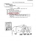
Test 3. Test circuit wire of affected tank.
Step 1. Dieconnect lead 28 (left-hand tank, pin B) or lead 29 (right-hand tank, pin D) from fuel
selector switch.
Step 2. Place battery switch to ON position.
Step 3. Place fuel selector switch (if equipped) to affected fuel tank.
Step 4. Set multimeter on 50-volt range.
Step 5. Connect multimeter negative lead to chassis ground and positive lead to pin B or pin D
on selector switch. Multimeter should indicate battery voltage.
a. If battery voltage is indicated, repair lead from switch to sending unit (para. 3-131).
b. If battery voltage is not indicated, go to test 4.
Test 4. Test fuel selector switch.
Step 1. Dieconnect lead 28 from pin A of fuel selector switch.
Step 2. Place battery switch to ON position.
Step 3. Set multimeter to 50-volt range.
Step 4. Connect multimeter negative lead to vehicle chassis ground and positive lead to
connector of disconnected lead 28. Multimeter should indicate battery voltage.
a. If battery voltage is indicated, replace fuel selector switch (para. 3-109).
b. If battery voltage is not indicated, repair lead 28
Thanks, Jim


