• Steel Soldiers now has a few new forums, read more about it at: New Munitions Forums!

  • Microsoft MSN, Live, Hotmail, Outlook email users may not be receiving emails. We are working to resolve this issue. Please add support@steelsoldiers.com to your trusted contacts.

glow plug controller bypass

donalloy1

New member
673
1
0
Location
Martinez Ca
well as usual small project turns into larger one. was hoping to get m1009 back on road today by doing what seemed to be a simple gp controller bypass. was unable to get current to gp's that's reasoning behind the alteration. here is what i did.

from blue wire landing on gp relay. landed two more conductors. one landed to ground and the other went manual switch. from other side of manual switch landed to ground. hooked batteries back up. so far so good. fired her up and smoke started coming off gp resistor pack on firewall? generator gauge is staying yellow?

hopefully i have not done to much damage? fired back up and still smokes from resistor pack on firewall. put meter on batteries and all I have is resident voltage 11.74 while engine is running. shut her down till i can get some advice.:deadhorse:
 

AgeOfDarkness94

New member
37
4
0
Location
Palm Springs, Florida
it sounds to me like you may have short circuited the relay resistors. I am by no means an expert, but perhaps the short still allowed the switch to reamin on after the relay was disengaged? post some pics if you can of the carnage so we can maybe see if there was indeed a fault in the wiring. Did you already do the doghead relay mod or was that what you were describing?
 

Blood_of_Tyrants

Active member
1,614
11
38
Location
Lebanon, TN
Why not just do the Doghead Relay mod?
I think that mod is to replace the cheap relay that is in the starter circuit, not the GP controller.

The simple answer to how to bypass the GP controller is to put in a momentary ON switch, remove the pink wire from the GP relay and route a wire from one side of the switch to the GP relay. Find a 12 volt source and route through a 2 amp fuse to the other side of the switch. If necessary you can ground the lt blue terminal of the GP relay.
 

doghead

4 Star General /Moderator
Staff member
Super Moderator
Steel Soldiers Supporter
26,246
1,177
113
Location
NY
You simply need to ground the light blue wire/terminal with a push button. The pink wire is the power for the relay.


The Doghead relay deal is an upgrade for the under dash starter relay. it has nothing to do with the glowplugs.
 
Last edited:

donalloy1

New member
673
1
0
Location
Martinez Ca
sounds like i TOTALLY misunderstood you doghead. interpreted doghead relay deal as gp controller bypass method. time for damage control! hopefully did not ruin gp resistor package? will suck up and move on. welcome to trial and error. nobody to blaim but self.aua
 

WARWAG

Active member
I think that mod is to replace the cheap relay that is in the starter circuit, not the GP controller.

The simple answer to how to bypass the GP controller is to put in a momentary ON switch, remove the pink wire from the GP relay and route a wire from one side of the switch to the GP relay. Find a 12 volt source and route through a 2 amp fuse to the other side of the switch. If necessary you can ground the lt blue terminal of the GP relay.
I misunderstood what he was trying to accomplish.
 

donalloy1

New member
673
1
0
Location
Martinez Ca
who has the abc method for dum __ts to bypass glow plug controller on m1009. want to go manual all the way. someday maybe go back to stock. need fail-safe process. going to undo what i have hooked up and start fresh. may have cooked gp resistor package? carnage is not photogenic. started smoking and turned off before all went to he__ in handbasket. :cookoo:
 

donalloy1

New member
673
1
0
Location
Martinez Ca
well it has taken me two working days to un__ck what i attempted to accomplish. wanted to simply bypass defective gp controller.

applying the donalloy gp controller bypass must have excited something that was asleep? removed what i installed and all is well again. she starts cold like a champ and is begging for a run. must have removed some dust ( smoke coming off resistor pack ).

front battery idle charging @ 13.77 rear @14.46. @ aprox 1200 rpm front 14.04 and rear charging @ 14.70. those numbers look pretty sound vs. tm. what do u all think. surprised i am not buying new alternators?

iam sure it will trouble me again. never get off that cheap. man against machine ya know. or for those that do not. we lose. sooner or later. will hook up monentary switch method off gp RELAY pronto in standby mode. so that if she acts up again will do roadside hookup. of course will test first.

sorry it took so long to report carnage or lack of. she will bless the bay area streets again tomorrow after two weeks incognito. respectfully, donalloy the m1009 gp circuit analiator...:evil:
 
Last edited:

charlietango

Member
Steel Soldiers Supporter
505
20
18
Location
Winnipeg
not to resurrect the dead here, but Im tracing a fault and my searches brought me to the moon and back. I have only a manual push button on my GP's. Doghead, this guy went wrong grounding the blue line then adding another ground off the manual switch correct? I read it twice and it seems he spliced the blue wire at the relay with two leads, one to ground and one to the switch. Whereas the switch too got ground off its second terminal. Just verifying the whole setup now as it was installed already when I got it.....
 

charlietango

Member
Steel Soldiers Supporter
505
20
18
Location
Winnipeg
mine is already done and has been for 7 years or more. Im tracing and sourcing out a problem and just making sure its all wired correct while Im going past....
 

5moker

New member
37
0
0
Location
Niceville/Florida
Mine had a push button when I got it. whoever did it clipped the pink and blue wire on the relay. Then took power from the resistor on the relay and ran it to a push button. from there they ran the next wire from the push button to the Pink wire connectinion. They also grounded the blue wire to a relay bolt on the firewall. It works fine for me. I will try posting some pics for ya tomorrow.
 

doghead

4 Star General /Moderator
Staff member
Super Moderator
Steel Soldiers Supporter
26,246
1,177
113
Location
NY
In stock form, simply add a(NO) momentary switch between the blue wire and ground.
 

charlietango

Member
Steel Soldiers Supporter
505
20
18
Location
Winnipeg
rgr, i had a bit of a panic when first going through but it appears they grounded the button back thru the firewall to near the GP relay. Looks all good. Metering today.
 

Warthog

Moderator
Super Moderator
Steel Soldiers Supporter
13,774
232
63
Location
OKC, OK
Mine had a push button when I got it. whoever did it clipped the pink and blue wire on the relay. Then took power from the resistor on the relay and ran it to a push button. from there they ran the next wire from the push button to the Pink wire connectinion. They also grounded the blue wire to a relay bolt on the firewall. It works fine for me. I will try posting some pics for ya tomorrow.
Just becuase it works fine does not mean it is the correct way to do it.

So you are saying that your are suppling power to the relay from the 24v GP resistor pack? If so I hope your relay is rated for 24v to the coil. Most are only rated for 12v.

Also your power wire to the push button is not protected by any fuse, only a fusible link. If the wire grounds out anywhere you may have a fire.
 

5moker

New member
37
0
0
Location
Niceville/Florida
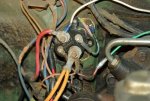
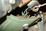
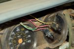
Only had mine about 6 weeks! Good call warthog!!! Have not adressed all the electrical issues yet (and I have a lot of it). Hear is an example of how not to do it! No fuse! This one was on a college campus. I didn't realize the kids kept it up!!! I have an automotive wiring guru coming this weekend! I will go with his opinion. I know he will freak when he sees some of the stuff like this ( yes I hav more)! I have put wiring on the back burner. My m1009 was over heated and had cold water dumped in it, destroying the motor. I installed a hummer motor with some small changes, IP oil pan vaccum pump ect... Trying to get it through paint this week and address shift problems and wiring this weekend! Here are some pictures of what was done to mine (at least they left me factory wiring)!IMGP3438.jpgIMGP3442.jpgIMGP3440.jpg I love how they wired in the gp light !!! Not how I would have done it. Guess it would work in a serious pinch. Of course then you would just jump the relay...
 
Top
AdBlock Detected

We get it, advertisements are annoying!

Sure, ad-blocking software does a great job at blocking ads, but it also blocks useful features of our website like our supporting vendors. Their ads help keep Steel Soldiers going. Please consider disabling your ad blockers for the site. Thanks!

I've Disabled AdBlock
No Thanks