• Steel Soldiers now has a few new forums, read more about it at: New Munitions Forums!

  • Microsoft MSN, Live, Hotmail, Outlook email users may not be receiving emails. We are working to resolve this issue. Please add support@steelsoldiers.com to your trusted contacts.

HF54 power steering for my M35A2

goodwithwood35

Active member
Steel Soldiers Supporter
327
51
28
Location
Bakersfield, CA
Over the past few years of owning my deuce, power steering was always on the top of my list of things I wanted to upgrade. Finally, after several months of research and looking over the options, I opted to go with the HF54 route pioneered by Gringeltaube. Another member, local to me, Seth-O was a big help in the whole process. I also had a few emails back and forth to Steve6x6x6 about pitman arm choices for the HF54. He also did an excellent write up. You can view their threads here:

https://www.steelsoldiers.com/showthread.php?114451-Ross-HF54-Power-Steering-in-my-Deuce (Seth's)

https://www.steelsoldiers.com/showthread.php?2909-Deuce-power-steering-conversion (Gerhard's)

https://www.steelsoldiers.com/showthread.php?15916-Power-steering-for-the-Deuce (Steve's and Gerhard)

I decided I wanted to go with the HF54 conversion because the box sat inside the framerail, like the originally equipped manual steering box. At the time when I was planning this out, I was running 395/85R20 Michelin XZL super singles and MRAP wheels. However, I ended up switching these out to 1100R20 G177's to get back some of the original deuce look. I felt I was getting too far away from the original look, as this truck is used in a lot of Veteran's events and honestly I like the dualed out look better. I think the G177's are a great improvement over the stock 900's and handle better than the 395's, but YMMV.

I did ponder full hydraulic steering, although proven reliable, I live in bleeding heart, sue happy California so I wanted a fail safe in case of a complete hydraulic failure. If I got in an accident and CHP/DOT found out I was running non-highway approved full hydro steering on the road they'd have a field day on me and open myself up to endless lawsuits (not to mention give all us MV owners a bad name/reputation). The HF54 does has the capability to be ported for hydro assist lines, perfectly legal and also useful for a hydroboost brake system, if I ever decided to do that, although I haven't really seen many of those conversions. From the write ups I've seen on the HF54, even with the wide singles, it has no problem moving them without needing hydro assist. Maybe I'll rig a steering sensitive beer can crusher to it, who knows.

So over the past 6 months, I have been acquiring the parts to do the job from various sources, mostly a popular auction site we all know and love.
  • I was able to find a Ross/TRW power steering box, HF54 series, part #542996 for $200. It said it was rebuilt and nicely painted when I got it, well, more on this later. Being that these boxes are pretty much obsolete, I went ahead and ordered a rebuild kit for it. This was $50.
  • I found the pitman arm for it from 99 Truck Parts (Canada). Part number D0HA-3590-J...this was $100 shipped to me, appeared in brand new condition. This of course was shortened to 7.5" center to center as Mr. G pioneered in his thread for the optimum deuce rotational capability.
  • I made my own drag link by using a few tie rod ends from a 70's Dodge truck. Part #ES304L and ES304R, right and left hand threads. I found these fit the pitman arm and stock deuce steering knuckle (which was retained from the original setup) perfectly. I picked these up for a steal at $20 for BOTH!! To connect these together, I went to the steel yard and found a piece of 1" solid round bar (~$20), welded on adjusting sleeves on each side (Moog ES3420S, $18 each). One side had the LH thread open, the other side had the RH thread open to accept each TRE respectively.
  • Since mounting this PS box required cutting/trimming the frame, I had to make a reinforcement plate, similar to Seth's and Gerhard's. I took a piece of 8" channel, 22" long, and cut off the lower leg to create an "L" shape. This cost approximately $30. For the mounting hardware to bolt this to the frame and to bolt the box to the plate, was about $50 from my local bolt supply house. I did have to purchase an 4" hole saw from home cheapo to cut the hole for the large sector shaft, as it protrudes into the frame rail. This was $22.
  • I was able to purchase a PS pump from a 5 ton, 800 series engine from another SS member, Capriceii, $250 plus shipping. This is the same pump that Mr. G, Seth, and a few other's have used. I believe it is also the same pump that the Waterloo kit uses. 1500 PSI and 5 GPM.
  • For the steering linkage, I used a 24" "DD" telescopic steering shaft made by Borgeson. Part #450024, $77. To connect it to the upper column, I used a Borgeson 1" smooth round X 1"DD U-joint, part #015268, $65. To connect to the box, I used a Unisteer #8050880 3/4"-36 spline x 3/4" DD U-joint, $68.
  • The upper column is a Gama Goat column. This allowed me to retain my horn button capability without doing too much engineering. I was able to find this for $30 shipped, brand new! I fit the original, cut down version of the OE steering shaft inside as the GG column wasn't quite long enough and had a female spine on it, I figured it would be easier to use the original shaft and shorten it to accept the 1" smooth U-joint, the deuce and the GG have the same diameter shaft, 1" round.
  • Of course with PS you won't need the 20" wheel, and to save some space in the cab, and my wheel was badly cracked, I splurged and purchased a new 18" 5 ton wheel for $100. My horn button assembly came apart in the process of removal, so a call to Big Mike's I had a new one for $20.
  • For the reservoir, I used a Nelson Exhaust #91048A, $80. It holds just over 1.5 quarts, and according to research others have done this is plenty of fluid. It also has a built in, easily replaceable, reasonably cost filter you can get off the shelf at most auto part houses.
  • 4 quarts of Type F ATF was $18 from Napa
  • Custom hoses and fittings cost me $80 from my hose supplier.
  • So, all in all, I had about $1300 into the system before I started. I did want to keep it under $1000, but I was satisfied I had just about all I needed.

I was ready to start my project, so all I needed was some time, not easy as a teacher and father of 2 and all the stuff that comes with running a household and such, but as a teacher summers are great, however in CA they are HOTTT!!! I wasn't really looking forward to doing this during the summer (My truck lives outside), but it was probably my most viable option. I made sure I had everything ordered in time for the break!
 
Last edited:

goodwithwood35

Active member
Steel Soldiers Supporter
327
51
28
Location
Bakersfield, CA
So as it turns out, my wife's family in Idaho was planning a get-together around the 4th of July. I politely opted out of that deal...so it was looking like she would be gone for a week. Being we have 4 chickens, 4 dogs, a cat, 2 turtles, a garden, etc. etc. to look after, it was a no brainer that someone should stay behind or burden someone to come over here several times a day to look after things...so I Roger'd up to do the dirty job ...power steering here we come!!! :whistle:.
 

goodwithwood35

Active member
Steel Soldiers Supporter
327
51
28
Location
Bakersfield, CA
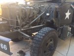
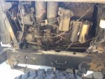
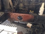
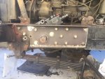
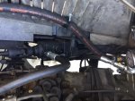
The obvious first task at hand was the tear down of the old system, remove the fender, the wheel, and lights. And buy a case of beer of course...Then remove the stock manual box. It came out easily WITHOUT jacking the engine, however this required separating and draining the halves of the box, and easily (dead blow mallet) pounding out the sector shaft. There is a drain plug in the box. Don't forget to unplug the horn wire. I also pulled out the 4 bolts holding the column in to the box, and pulled out the worm gear assembly. Maybe took 30 minutes at most. Much easier than jacking up the engine, as I have nothing to do that with anyways unless I rented something.
IMG_4042.JPG
image2.JPG
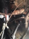
Removed the OE drag link, pitman arm, and ball-stud to steering knuckle.
drag link removed.JPG
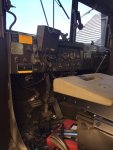
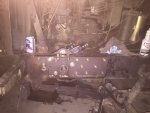
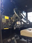
On to the interior...removed the wheel, OE column and accessories attached to it.
interior.JPG
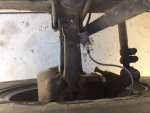
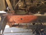
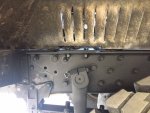
Finally, removed the old manual box reinforcement plate by punching and pounding out the hot rivets. No turning back now!!! Gave them a good shot of rustoleum metal primer as this area hasn't seen daylight since 1965 sometime.
old box removed.JPG
Now on to building the new reinforcement plate (To be continued).
 
Last edited:

tommys2patrick

Well-known member
699
272
63
Location
Livermore, Colorado
Thank you for starting this thread. Like you, the addition of power steering is at the top of my list for modifications. I am really looking forward to your progress. About how many hours do you have into the tear down at this point?

By the way, I like your anti-dive seat belt/seat set up.
 

goodwithwood35

Active member
Steel Soldiers Supporter
327
51
28
Location
Bakersfield, CA
Build Day 1

Ok, so onto the reinforcement plate fabrication.

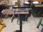
So since the HF54 requires some cutting of the frame, and it sits at a 30 degree angle, and obviously bolts on differently than the OE manual steering box, fabricating a strong reinforcement plate is a MUST. I went to the steel yard and found a 5/16" piece of 8" channel. I began by measuring the distance from where the fender bracket sticks out, to the tie down point on the frame (The handle looking thingy). I got 22", so I cut it down to that length, and also removed the lower leg of the channel as it would get in the way of the steering components once they were installed. I suppose I could have just cut out what was needed for them to clear, but I figured the plate would be plenty strong already and wanted to keep the look as original as possible.

Here is a pic of using the OE steering reinforcement bracket as a template for the holes to drill into the new plate (new plate is positioned on the frame side). Since the stock holes were 3/8" for the box mounting and 5/16" for the plate rivets, I used the respective drill bits to center the holes onto the new plate, then punched them with a spring loaded punch, then gradually stepped them up. Starting with a 1/8" bit, then 1/4", then used a uni-bit (Christmas tree bit) to finish the job. I don't have a drill press, so I used a cordless Dewalt drill with good results, although not as "fun" as a press. I used a lot of cutting oil and took it slow. Finally, I got all the holes to the 1/2" I needed for the plate mount bolts. This was pretty time consuming and was probably the most boring part of the job.
plate fab.JPG

Once all the holes were drilled to mount the plate on the frame, I used as many as the original holes as possible. Some would interfere with the new Ross box, so I couldn't use those. I added a lot of holes as I didn't want any frame flex while steering or something coming loose on me. Next it was onto the holes to mount the box. This proved challenging as the box doesn't come with a template. So, being a CAD/Drafting teacher, I measured the distances and made a template with AutoCAD. I laid this on the reinforcement plate and began to drill away. This required three, 9/16" holes. The 4th hole would have to be done in a top bracket, as a separate piece, as many of the others that have done this project have done. Once that was done, I test fit the box on my bench and it fit perfect the first time (YAY!). The box mounting bolts are 9/16x2 Grade 8 NC thread with washers to better distribute the force onto the plate.

Now I had to mount the plate to the frame temporarily. I used the hole on the top left and the original bolt that sticks out of the frame that is a brakeline and airline clamp inside the frame rail. It is right next to the tie down loop, I figured this would be a good one to use. I made sure everything was square and level, and started marking bolt holes and lining things up. Clamped down good...Now for some more drilling...my poor drill. The OE holes were enlarged to 1/2" for the plate mount, the box mount bolts were drilled to 9/16" (3 of these), and the new bolt holes (7) were drilled with the plate in place. This took quite a while, and many beers later.

lining up the plate and enlarging holes.JPG
lining up the plate and enlarging holes 2.JPG


The holes that I added were predrilled on the bench, and matched up on the frame and drilled through. The sector shaft hole on my new plate was a 2" hole I cut with a torch on the bench. A hole saw or a plasma would have worked too, but I'm old school, and don't own a plasma (It's on my list).

I used 1/2x1.5, grade 8, fine thread with nuts and lockwashers. Pretty much the same bolts I used on the winch install so everything would match up. There were a few bolts that went through the crossmember (where the rivets were once shared with the OE plate) that were 2" long instead of 1.5". This crossmember would prove difficult later on. Finally, all the bolts were done, and test fit. Now, to cut the large, 3.75" hole in the frame. The HF54 has a "nose" protrusion for the sector shaft housing that goes about 3/8" or so beyond the mount flange, so this large hole allows for the nose to sit inside the frame rail and be flush mounted perfectly. Fun...fun...fun. Lots of oil, it was over 100 degrees, mid afternoon at this point, but got it done with a cheap home depot bi-metal hole saw and my Dewalt drill. It came out pretty good. I also used my CAD software to make the template for the big and the little holes in the frame and reinforcement plate. The HF54 sits at a 30 degree angle to the frame.
drilling holes.JPG

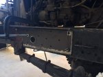
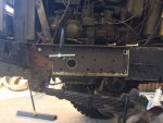
Unfortunately, my drill died. This was the last hole she would ever drill. Tried to drill some burrs off another hole and NOTHING!!! This was kind of hard on a cordless drill, next time I'd use an electric. I pretty much smoked the hole saw too, which I expected; it was a cheap non-carbide saw. Oh well, time to upgrade to a 20v brushless!!! I cleaned the hole up with a die grinder and carbide bit. Now to bolt the bracket on, and test fit the box! To do so, I had to move a lot of things in the frame rail. The airline that comes off the compressor, which was leaking and had to be repaired anyways from a frame chafe, and years of previous owners doing "booger" solder jobs on it. Also the fuel line from the primary FF to the IP was in the way, so I disconnected it and repositioned it temporarily. I also had problems clearing the front crossmember. Apparently, as Seth-O found in his project, I have the older A1 style front crossmember (the one without the hole in it for the winch driveline). So I had to do some trimming on that, and welded on a reinforcement to the front. It was still held on by 3 of the original rivets, but I just wanted to make sure I didn't cause any problems later. But finally, around dinner time, I got the box in with 3 of the mounting points touching the frame. (YAY!) That dang thing was heavy and hard to do from under the truck...but was too hard to do by myself from the top, I didn't want to drop it!!! To do this, I also had to trim the frame as Gerhard did on his. *See Gerhard's writeup for example* I actually used a weight lifting bench and pressed the box to position like I was doing a close-gripped bench press, since the deuce frame is taller than I could reach laying on the ground. Once again, I was doing this without help, and I don't have the wingspan of Michael Jordan.
box installed and bolting up.JPG

So now, to complete the box installation, all I had to do was fab up and mount the top plate for the mounting hole that sticks above the frame due to the 30 drag angle the HF54 sits at. I made this out of a piece of 5/16" angle I had laying around, and I rounded off the edges to make a more sleek looking install. So after about an hour with a torch, grinder, Another 9/16" hole was drilled appropriately, and 2 more 1/2" holes were drilled to fasten it to the frame plate using 1/2x1.5 grade 8 fine thread bolts and nuts and lock washers. Now to mount it on the truck.
top bracket installed.JPG
After this was complete, it was well after 8pm. I worked about 10 hrs this first day of the build. It was hot, I was a mess, and decided to call it a day, have another beer and hit the hay. Of course after a long HOT shower as I smelled like farm animal that was lit on fire. Tomorrow would be the pump install, and if time allowed the reservoir too.

'Till tomorrow!
 
Last edited:
goodwithwood35

Active member
Steel Soldiers Supporter
327
51
28
Location
Bakersfield, CA
Day 2

Ok...feeling a little sore, made a power breakfast, and back at it at 8am. I wanted to get the pump and reservoir done today so I could have the hoses made. I didn't realize it but our hydraulic shop in town was going to close for the long 4th of July weekend (Sat-Tues!), so I needed to get this done or the project would be delayed. The goal was to have it done and tested before the wife got home...

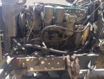
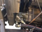
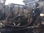
First thing I did was remove the timing cover blank where the pump would mount. I also trimmed away the radiator shroud. I was able to do all this (Carefully!) on the truck without removing the radiator using an air cutoff wheel and a dremel tool. The pump mounted pretty straightforward using a new gasket it came with. The cutout I made turned out perfect and the pump went in from the bottom of the truck easily.

radiator.JPG

To mount the reservoir, it came with 2 nice brackets that ended up going right into the 2 unused "speed-nuts" on the firewall above the steering column. I did have to re-route the wire harness, but it fit perfectly using some 1/4" grade 5 NF bolts and washers. Since the cap stuck up a little high, I trimmed one leg of the channel that supports the span under the hood, about 3". I wanted the reservoir to use this location rather than drilling more holes in the firewall, and keep the OE look as much as possible. It also allows for easy checking and filling of the reservoir. It came out pretty clean. Now...quick shower, lunch, and off to the hydraulic shop!!!

-The ports on the pump are 3/4" NPT for the suction, and 1/2" NPT for the pressure. There is also a 1/4" NPT relief line that I plugged per previous research on write-ups from SS that have done PS installs, it isn't really needed unless you abuse your system.
-The ports on the box are -8AN O-ring boss for both the pressure and return.
-The ports on the reservoir are -8AN O-ring boss for suction and return. There is also a 3/4" o-ring boss that I got a plug for in the reservoir. I suppose you could put the relief line here, or add a temp gauge.

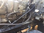
So using some bailing wire, I mocked up the hoses, measured it, and had them made at the shop while I waited. Not knowing if I would add a cooler in the future, I sort of rigged the return line for now using clamps. I wanted to make sure I was running at decent temperatures first before I fiddled with needless equipment. So I had a $20 hose made for now for the return, if needed, I would re-engineer that portion later. I used swivel connections and/or adaptors at all the connection points to make things easy to install in the cramped engine bay. I had the hoses quickly installed and they fit well. The return hose, I will either re-engineer later on or use it to add a cooler either under the radiator or in front of it somehow.
hoses and reservoir.JPG
pump.JPG

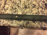
It was still early in the mid afternoon, so I started fabbing up the steering column. I completely disassembled the GG steering column to fit the original, shortened M35 shaft in it. I also had to make a hole in the M35 shaft similar to how the GG one has for the horn wire and brush. I was sick of the heat, so I did this in the AC house on the ol' lady's nice kitchen counters LOL.
GG column.JPG

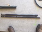
Here are the 2 shafts, side by side. The GG one with the female splined connection is on top. I chopped the M35 one about 6" longer than the GG one so I would be able to connect to the intermediate shaft inside the engine bay. The GG column isn't long enough to reach in there, and I wanted to use my existing EGT and Boost gauge cluster I got from Peashooter a few years ago, so pushing the column down more wasn't an option. I also made a hole in the M35 shaft for the GG brush and wire connector for the horn. I wanted to use the original horn button setup, and not have to add an additional horn button later.
shafts.JPG

At this point, I called it quits for the day, after about 6-8 hrs. My FIL came over and after a few beers and yacking, a few more beers, and more shootin the you know what, time and the beer got the best of me. Tomorrow would be another big fabrication day so I wanted to make sure I was really at my best for modding the pitman arm and making the drag link.

Time for some ESPN and some shut eye...
 
Last edited:
goodwithwood35

Active member
Steel Soldiers Supporter
327
51
28
Location
Bakersfield, CA
Day 3.

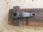
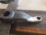
Now for some real fun. According to Gerhard's research, who's wisdom and skill I envy, I needed to make my pitman arm 7.5" from sector shaft hole to drag link hole. Mine was 9.5" center to center. So I chopped 2" out of the arm (scary!). I beveled the cuts for a double butt-weld using a MIG.
arm.JPG

I left a 1/16" root gap, and started with a good root pass. I grinded and buffed this down, and did a hot pass on each side, allowing to cool in between passes. Each proceeding fill pass was followed up with natural cooling, grinding and buffing. Finally, both sides were done. I grinded the caps down, and finished it with a flap wheel sander. This was pretty time consuming, but I wanted it done right, and look factory. I used to work for a weld inspection company, so I've learned a lot over the years about proper welding along with many classes in college (I'm an engineering major). I was pleased with the results
weld.JPG

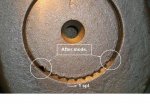
Finally, I removed one of the teeth from the 10-tooth splined PA, as Gerhard recommends in his post to properly "clock" the arm on the sector shaft to get the full range of motion from the Ross box (Stolen PIC this is yours Mr. G!)
Gerhard mod to PA.JPG

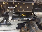
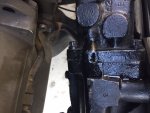
I then began fabbing the drag link. I made sure the HF54 was in it's neutral position. A 12-pt 11/16 socket fit right over the box's input shaft, and I counted the total turns left to right (5). Then went back 2.5 turns to find the center point. I then mounted the PA, and ensured the wheels were centered. Then I placed both TRE's in their holes and measured what I would need to cut the drag link steel rod to. I cut the rod, and installed the adjusters, leaving a slight amount of slack in case I needed to adjust the length. I installed the TRE's, and I did have to turn them a few turns to make it the length I needed, then welded the adjusters on permanently. Then test fit the assembly and it fit perfectly.
pitman and DL installed temorary.JPG
I liked the fact that I could adjust the DL in the future without removing the DL by loosening the clamps and spinning the center section, due to the opposing RH and LH threads on the TRE's.
 
Last edited:
goodwithwood35

Active member
Steel Soldiers Supporter
327
51
28
Location
Bakersfield, CA
Day 4-5

So now that the outside of the truck was done, and the completed steering column was waiting there, looking lonely, I decided to install some of the interior components. I installed the upper column I completed the previous day in my kitchen LOL. I also put together all the original things on the steering column, the new 18" wheel, the turn signal, the instrumentation, and made sure I got good grounds for the turn signal and horn to operate. Still waiting on the horn assembly to arrive, but I'd do that later as it wasn't important now.
upper steering.jpg
I also had to make a support for the firewall side of the upper column, out of a small piece of angle iron and a 1.75" exhaust clamp. The original setup was supported inside the engine bay directly to the manual box. I used star washers on this clamp, made sure I had metal to metal contact, and drilled 2 new bolt holes to mount the bracket to the firewall, also using star washers and metal to metal connections. I then welded on the upper, 1" smooth to 1" DD U-joint to the steering shaft. The steering column also sits at a 30 degree angle to match the angle of the HF54 box. I used a magnetic angle finder to determine proper placement of these components.
inner bracket.JPG

upper steering 2.JPG

After much resistance from a seller and deal gone awry on e-pay, I finally got my intermediate shaft and installed it, just in time to test the system and bleed the air. I had to cut it down about 4" shorter, but it fit and worked perfectly once I installed the lower U-joint at the box end. The seller ended up refunding my money when I told him I would leave negative FB...it took over a month to get it and he lied and said he sent it but refused to provide tracking. The first time he just sent an empty box...UGH!!!
int shaft.JPG

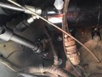
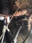
So, at this point, I filled up the system with Type F PS fluid, as Ross suggests. I also disconnected the PA from the sector shaft so I could turn the box end to end to bleed all the air out without a load on the system. Once the reservoir stopped foaming and the fluid level remained constant, I reconnected the PA, and put the wheel back on the truck to do a "loaded" test of the system. It steered beautifully once the remaining air was out. I used about 3.5 qts of fluid, similar to what most others who have done this have used. However, I did have a decent leak from the upper side of the steering box. Grabbing a schematic of the HF54 box online, it was where the O-ring is where the adaptor plate connects to the body of the box, on the return fluid from spool valve to piston housing port. I was pretty bummed at this point as my system was working great otherwise. I got online and found a rebuild kit, unfortunately I now had to wait for it to show up. I originally had ordered a kit, but I wanted to use that as a spare in case it happened in the future, and wanted to make sure the kits were the same before I tore into the box to make sure I wasn't going to have a mismatched kit and confuse the heck out of myself. Here if you look where the 2 halves of the box fit together, where the little bump is the bloody leak...
leak.JPG
As I now had time to wait, I noticed my belts, hoses, and radiator coolant was nasty, and well worn. A quick call to big mike's, real custom trucks, and Napa, and ordered a new set of hoses, belts, a coolant filter kit, t-stat, gasket, and seal. I also took out the radiator completely, as it is nearly impossible to change the belts and hoses without doing so, and had it rodded out. Turns out, it was 30% clogged with crud. I flushed out the block with a rag (to plug the hole) and garden hose, and more crud came out of both ends. YUCK my poor engine!! I flushed it for over 20 minutes until it was clear using low water pressure. I'm glad I decided to put a coolant filter on. So this took the better part of a few days to wait for parts and have the radiator done, and put it all back together, but it's a good feeling knowing I would have all new belts and hoses. She was running a tad hot also the last few times, and it regularly gets over 100 degrees here in the summer...so good insurance. I can't believe I let my belts and hoses get to that level of wear. My 6 year old probably could have pulled one of my Alternator belts off the pulley without loosening the adjuster. Dang things are so hard to see on this truck. I guess that explains my squeak for about 30 seconds after startup!

Once that was done, my wife had returned from Idaho...bummer I didn't get it done in time. At least I had time to clean up my mess and tools everywhere, and clean up all the oil and antifreeze. It looked like an operating room after a mass casualty out there. It was good to have my family back home. I was sunburned and they looked at me funny, but it was nice. Back to working on this thing at night I guess after everyone goes to bed. I have 2 young kids that keep us pretty busy.
 

Attachments

Last edited:
goodwithwood35

Active member
Steel Soldiers Supporter
327
51
28
Location
Bakersfield, CA
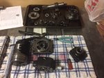
So now to the box rebuild, since my kit came in. Sure enough, same kit, just different manufacturers. It was good insurance to know I have another on the shelf just in case. The Ross manual I got online (60 pages, PDF) gave a VERY straightforward disassembly and assembly and testing instructions. The tear down went pretty well. When I say tear down, I mean every little nut, bolt, washer, seal, and ball had to be removed. I'm glad I printed this manual out for future reference. It took several hours to tear it down...
box teardown.JPG

And probably a solid 4 hrs to put it back together with new seals. What I found was either a machining error on my adaptor plate, or the factory used improper seals. But there is no way the o-ring could seal that flange together. The boss was .080" deep, and the o-ring was only .062 thick. Everything else in the box checked out great, within tolerances, and all the other O-ring bosses were adequately sized to fit the new O-rings. The only leak I had was at the return line from the spool valve body to the piston case. So another trip to the hydraulic shop, no one made a flat O-ring that was 1/2" OD x 3/8" ID and .100" thick (CS). This is what I would need to seal a boss that was .080" deep. So digging through their bins, they found what is called a "quad-ring" for valve faces. It was 1/2"OD x 5/16" ID x .102"CS. It was perfect. And better yet, it was FREE! I grabbed 2 of them in case I needed another in the future. The ID was different, but the fluid transfer hole was only 1/4". I prayed my luck would pay off!

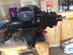
I got it all put back together.
box back together.jpg
box back together 2.jpg

Tested it out once again, using the recovered fluid (that I ran through some filter cloth), I only lost about 1/2 quart so I had to add the remaining fluid from when I did the job originally. I made sure to put on my shopping list a few extra quarts of Type F to have around in my truck's tool box. One more thing to haul around (The joys of deuce ownership!)

NO MORE LEAKS ... YAHOO!!! I could have kissed a man I was so happy (Not really, but you know what I mean). Gave everything a quick shot of rustoleum flat black...

Now for a real road test after bleeding the system, and making sure the coolant was topped off, which is always a PITA. I put the fender back on finally, along with all the wiring that had to be disconnected. I mounted the hose to the fender with a clamp and cut the notch in the inner fender to account for the frame bracket. Checked all the lights and grounds...everything worked. Looking through the fender, an untrained eye could never tell it wasn't a stock deuce.
hose mount.JPG
notch fender.JPG

The truck drove beautifully. There is still some air in the system, which was not there the first time before the leak. If I have to, I'll remove the PA and force it from stop to stop. I think I was a bit EASY on the box as I just rebuilt it, and it was my first time ever messing with a PS box internally. The hardest part was all the little ball bearings had to be carefully inserted. There was drive balls, and chaser balls, which had to be inserted into the spool valve alternating big, small, big, small. They was only a .0005" difference in their size. Talk about precise!!! And no, they aren't color coded or labeled if they have been in use! You have to measure them with a fine micrometer, luckily I was able to borrow from a machinist friend, as my china freight one wasn't that accurate.

I did have to make a sector shaft adjustment, which was easy to do since I had the HF54 manual. It was only about 1/8 of a turn off and it did the trick. It took a lot of the darty steering and bump steer away.

I love my power steering and the way the truck drives now. So nice to drive. Sitting still, it can turn the G177s as easy as it is to turn my wife's SUV tires lock to lock in the driveway. No rubbing on steering components, on a stock deuce wheel with 1100-20 G177 tire, a full, locked out, right hand turn the pitman arm to draglink castle nut is about 1.25" away from the sidewall of the tire. Those that put 395's on stock deuce wheels may have some rubbing as the stock wheel sits farther inside the fender. However with an A3 or MRAP wheel they push to the outside the fender lip a bit more, so I'm sure this would eliminate the rubbing.

done.JPG

Fluid temps never climbed above 180, under HEAVY loads of steering while NOT moving and that was with a 101 degree ambient temperature so I am happy with that. After driving around a few neighborhoods, it didn't get over 170 on the return side. I put a gauge on the pressure side and the pump never exceeded the Ross spec of 1500 PSI when totally locked out. Even better!
 
Last edited:
goodwithwood35

Active member
Steel Soldiers Supporter
327
51
28
Location
Bakersfield, CA
Forgot to mention, before I put the system back together, I did the Gringeltaube method of grinding down the spring brackets 5/32" to correct the caster on the front axle. I also replaced my u-bolts with a custom made set (local spring shop) and added 3 leaves to level the truck out more. It now sits level at the fenders on flat ground. I only had a 10 leaf pack and now it's a 13 leaf. My caster now sits at 4.5 degrees POSITIVE. My steering is great, no bump steer, and returns to center (recovers) like it should.

Have not taken it off road yet to test the "deuce manual steering thumb remover" drill yet. Right now I'm just enjoying the ride...

I can't thank Seth enough for all his help, and Mr. G enough for pioneering this mod. We got some talented folks in this forum!

And 98G for the sweet new G177s! Love the look and the ride!

--Mike
 
Last edited:
goodwithwood35

Active member
Steel Soldiers Supporter
327
51
28
Location
Bakersfield, CA
Thank you for starting this thread. Like you, the addition of power steering is at the top of my list for modifications. I am really looking forward to your progress. About how many hours do you have into the tear down at this point?

By the way, I like your anti-dive seat belt/seat set up.
Thank you,

Those are modified MRAP jumpseats with 5 point harnesses similar to a kids carseat. I modded the stock spring base and the passenger bench to accept 3 seats wide. I will end up selling the center one for a shorter seat as it blocks my rear window.
 

goodwithwood35

Active member
Steel Soldiers Supporter
327
51
28
Location
Bakersfield, CA
While waiting for my belts and cooling system parts to show up, since it was right there I did some PM on my IP. I replaced a few seals and hoses to it that looked old, as getting to them would be difficult later in without removing the entire IP or PS box. I also bypassed the FDC and deleted the flame heater. I spent a couple bucks on some fittings, DOT hose, and replaced the injector line with the tee in it with a straight section of tubing and new ferrules. It looks like it was never there! Don't have a use for it in CA anyway and don't run much WMO in my fuel.

My IP was previously turned up a whole turn after I installed my Waterloo 5th gear. So after the FDC was bypassed my goodness this thing screams. Haven't pulled any hills yet but on flat land I'm now getting 14 psi boost on my C turbo, TD block, updated head gaskets. EGT is about 850. I suspect it will climb closer to 1200 on a grade, as opposed to 950 before. I'm getting darker smoke now when accelerating (not just when first shifting). It's mostly clear at idle. I'll more than likely turn it down some once I play around more.

I also relocated my turn signal flasher box to the firewall. I've replaced 3 of these in 4 years and not many miles, so I hope the less vibration of the firewall helps this. That fender rattles and vibrates around like a orbital sander.


Sent from my iPhone using Tapatalk
 
Last edited:
marchplumber

Well-known member
Steel Soldiers Supporter
3,795
2,819
113
Location
Peoria, Illinois
Thanks for the thread, the tech info, and for giving credit to those that helped and "did before" what you have accomplished! Quite the write up and a thoroughly enjoyable read!
 

Clay James

Member
524
4
18
Location
Reno/NV
Great thread. This is also very high in my priority list on my 109. I've been researching this and searching for parts the past few weeks. I spend hundreds of miles at a time in the 109 followed by hours of offroading getting to camping spots and that manual steering with 395s on the technical stuff makes me tell passengers to get the liquor ready for when we stop.
 

goodwithwood35

Active member
Steel Soldiers Supporter
327
51
28
Location
Bakersfield, CA
Great thread. This is also very high in my priority list on my 109. I've been researching this and searching for parts the past few weeks. I spend hundreds of miles at a time in the 109 followed by hours of offroading getting to camping spots and that manual steering with 395s on the technical stuff makes me tell passengers to get the liquor ready for when we stop.
Thank you!

LOL...yeah I had 395's I know your pain. It would take a come a long to turn the wheel at a dead stop!!! The G177s definitely helped, and the hub lockouts, but I still wanted true PS for when I daily drive it to work through town. Hope to take it on some off road camping trips when my boys get a bit older.

If I can find a decent AC system install that I like, that will be my next engineering job...but seems like a lot of non-factory looking modding. And I'm not very knowledgeable on HVAC to jump into that without a lot of research.


Sent from my iPhone using Tapatalk
 

clinto

Moderator, wonderful human being & practicing Deuc
Staff member
Administrator
Super Moderator
Steel Soldiers Supporter
Supporting Vendor
12,596
1,132
113
Location
Athens, Ga.

goodwithwood35

Active member
Steel Soldiers Supporter
327
51
28
Location
Bakersfield, CA
That's an awesome truck. Radials, P/S, O/D, lockouts, winch, etc. Very nice work.

Thank you!! I just restored (once demilled) a M66 gun ring to install next. It's completely functional again. Just sick of drilling for a while, and 100 something quarter inch pop rivets for the cab reinforcement plate don't sound fun right now in that hot cab after all the big holes I drilled for this last job. I'm also working on a gunner's hatch for my hardtop. I got a few ideas sketched out in CAD, once school starts back up and is in autopilot I can finish my design. I want to refrain from using the hole with the canvas cover and keep it all steel. Maybe a winter project. Wife's talking another Idaho trip to see some snow, LOL. And if I can figure out a good product to preserve my canvas cargo cover, I'll put that back on. But CA weather is beating it up. When I got it, it was sealed up in the original crate since the late 60's. So it's sad to see it drying out, and even sadder to see it sit in the garage collecting dust.


It won't make any difference. They're junk.

https://www.steelsoldiers.com/showt...sher-relay-civvy-conversion-how-to&highlight=
Well, darn it! Well, I've always hated the location of it regardless and now I can easily change it by simply opening the side hood door like when I check my remote brake reservoir. Maybe I'll have to design a more robust one with my electronics colleagues! Sure someone's been there already though.


Sent from my iPhone using Tapatalk
 
Last edited:
goodwithwood35

Active member
Steel Soldiers Supporter
327
51
28
Location
Bakersfield, CA
Another thing I did while I was there was replace a section of the copper airline off the compressor. It had been leaking since I got it due to a frame chafe, and previous owners or the military tried to solder a booger on there to stop it. I had to re-route it around the steering box and ensure enough room for the winch driveline. So this was done while I was waiting for parts. I went around the front crossmember and under the steering box, then back inside the frame rail to connect to the original, serviceable line with a solder connection. I used HVAC solder for this and a Oxy-Acy torch. Home Depot had everything I needed to make the repair, I had the solder rod from another job years ago when I put a new filter in my house AC unit.

I then reconnected the fuel line that was previously removed and tucked the electrical back into the frame for the lights and horn wire. The fuel line didn't need to be rerouted, it tucked back in nicely.


Sent from my iPhone using Tapatalk
 

clinto

Moderator, wonderful human being & practicing Deuc
Staff member
Administrator
Super Moderator
Steel Soldiers Supporter
Supporting Vendor
12,596
1,132
113
Location
Athens, Ga.
Well, darn it! Well, I've always hated the location of it regardless and now I can easily change it by simply opening the side hood door like when I check my remote brake reservoir. Maybe I'll have to design a more robust one with my electronics colleagues! Sure someone's been there already though.
Click on that link I shared. We've already designed a robust replacement.

I'm putting off a cab brace install for the same reasons. I need the brace in order to install the M44A3 3 point seat belt system. A lot of work.
 
Top
AdBlock Detected

We get it, advertisements are annoying!

Sure, ad-blocking software does a great job at blocking ads, but it also blocks useful features of our website like our supporting vendors. Their ads help keep Steel Soldiers going. Please consider disabling your ad blockers for the site. Thanks!

I've Disabled AdBlock
No Thanks