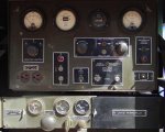
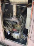
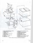
Check your flame switch to see if it's stuck (will require disassembly). Also check the on off winterization switch behind the operators panel.
The fuel regulator in attached/inside the winterization unit. The device you are referring to is the electric fuel pump for the winterization unit (easily serviced by disassembly). The winterization is a preheater so it's needs an electric fuel pump.
If you have the original dc generator and regulator on the genset, those are the 19 amp units and are weird. What you know about the 25 amp units does not 100% apply to the 19 amp units. The output should be 28.8 volts and the original gauge has the 28.8 volt tick in the green zone. You will need to adjust both the amperage cutout and voltage solenoids in the regulator to get it correct. Disconnect the battery before you remove the cover, don't ask me how I know...

You must have something wrong with your primary fuel filter as it will filter 100% of the junk very well, perhaps it is junk after the main filter. There is also a backup screen in the fuel pump you should clean for obstructions. I had to remove my gas tank and thoroughly clean it, then things were fine. When the carb is adjusted correctly, it will perform very nicely. Electric choke elements are still available if you want remote starting.
Paint: I scuffed what was there and sprayed on the correct color I got from ... was it Rapco or Army Jeep Parts? I can't remember. I painted everything before reassembly. The panels are aluminum and the frame is steel. I used an etching primer for anything I took to bare metal and used the Vietnam era dark OD color (1957 to present?). It was not a perfect match, but it was close. It had been painted twice in the military and both those colors were not a perfect match either.
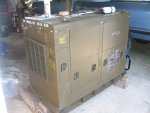
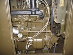
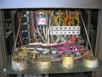
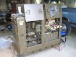
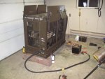
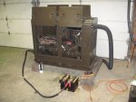
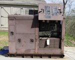
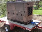
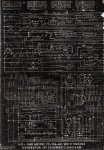
No, L0 is NOT the ground. The frame is ground and the grounding post is on the left front of the frame. L0 is the neutral (and they are not the same thing). The supplied side will need it's own ground like modern NEC or NFPA code. You should have a wiring diagram on the genset on the left front door. THE WIRING DIAGRAM IN THE MANUAL HAS ERRORS. Use the genset wiring diagram for correctness. If you don't have one, I'll post the manual one, but beware. I assume you have the change out boards that change from three phase to single, 120, 208, and 240 (image 2345 above). I would not assume the correct one is installed until I saw it with my own eyes. For the 120/240 single phase board, it's terminals L0, L2, and L3.
Get yourself some manuals. All the proper grounding requirements are in them.
Good luck. You have a great genset that will last forever and is easy to fix in a pinch.
Please post pics of your progress!!!!!
Allen
PS I question whether 10kW can handle a 3 ton ac and electric appliances all at once, but you tell me what happens when you load it up. The generator itself can probably approach 17.5kW, but the regulator and controls will not. Also, the main relay is set at just below 60 amps to trip. So either this little buddy does more than I give it credit, or you are doing some of your own mods. My place has a 5 ton heat pump and electric appliances so I manage my loads very very carefully.
![81QSCI09054041[1].jpg 81QSCI09054041[1].jpg](https://www.steelsoldiers.com/data/attachments/104/104660-555df759e02539026a9962ac50ad6144.jpg)
![81QSCI09054041A[1].jpg 81QSCI09054041A[1].jpg](https://www.steelsoldiers.com/data/attachments/104/104661-55abd8c2401cbcfeafded3ea5d6bbbe3.jpg)
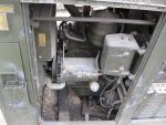
![81QSCI09054041[1].jpg 81QSCI09054041[1].jpg](https://www.steelsoldiers.com/data/attachments/104/104660-555df759e02539026a9962ac50ad6144.jpg)
![81QSCI09054041A[1].jpg 81QSCI09054041A[1].jpg](https://www.steelsoldiers.com/data/attachments/104/104661-55abd8c2401cbcfeafded3ea5d6bbbe3.jpg)


