Elektroman99
Active member
- 169
- 138
- 43
- Location
- Siegburg, Germany
M1009, 6.2 Diesel - Check generator 1 and generator 2.
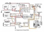
The indicator light of the "Generator 2" does not light up. But it also does not light up when I initiate the starting process of the M1009 by turning the ignition switch. Check light comes on before starting the engine. However, I know that when it gets power, the bulb in the dashboard / display is on.
OK, searching the internet I found the following video:
Now I wonder if there is a logical error test sequence here as well, from the TM? - Since I did not find one in the quick sighting. -
Then I wonder which devices / components I have to read / measure individually with current testers to get a clear statement about the functionality of the generators "1" and "2".
I can as seen in the YouTube video, each measure the batteries individually and together.
Then my question would be what value would I need to check on the generators and how?
So the question would be:
Best regards
Elektroman99
The indicator light of the "Generator 2" does not light up. But it also does not light up when I initiate the starting process of the M1009 by turning the ignition switch. Check light comes on before starting the engine. However, I know that when it gets power, the bulb in the dashboard / display is on.
OK, searching the internet I found the following video:
Now I wonder if there is a logical error test sequence here as well, from the TM? - Since I did not find one in the quick sighting. -
Then I wonder which devices / components I have to read / measure individually with current testers to get a clear statement about the functionality of the generators "1" and "2".
I can as seen in the YouTube video, each measure the batteries individually and together.
Then my question would be what value would I need to check on the generators and how?
So the question would be:
- Is there to check the display lamp generator 2 a logical error test sequence gives from the TM?
- What current values need to be measured at "not running" and at "running" engine (6.2 diesel) at the genea4rtoren "1" and "2" where to confirm that they are not defective?
Best regards
Elektroman99


