Keith_J
Well-known member
- 3,657
- 1,323
- 113
- Location
- Schertz TX
Does your M35 not run at all? No fuel? No throttle? This might help you fix the problem.
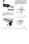
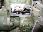
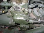
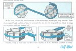
Remove the two screws securing the engine stop control to the injection pump. Attempt to move the control mechanism, it should move FREELY. If it doesn't, you need to pull the control lever assembly. See image 1929, two standard slot screws. See image 1928. The twisted wire (safety wire) needs to be cut, note the direction and wrapping. Once the two screws are removed, pull the clevis clip off the control rod. Now the control assembly can be pulled. Some diesel will spill so catch it. Also, the pin (item A on figure 3-47) is loose, DO NOT LOSE IT!
With the unit pulled, check the rotation of lever in the hub, it must be loose. Solvent will help but if that doesn't work, the lever CAN be disassembled. Bend the tabs off the nut, holding the shaft with a 3/8 open end and turn the nut with a 7/16" wrench. The lever is pushed on splines on the shaft, measure the lever angle with respect to the flats on the shaft. Making a thin scribe mark will help reassembly, this angle MUST BE PRESERVED!!!
Once measurement has been made, push the shaft out of the lever and clean the shaft/hub to allow for free movment. There is NO SEAL on this shaft, only precise machining keeps fuel from leaking so ANY DIRT will cause problems.
When reassembling, the number on the lever should be visible, usually a "17". And the splines will align in the exact position, you need to be close. This is a tricky feel operation.
Once the unit is reassembled, remember the original position (take pictures) and reinstall. A dab of grease on the pin pawl (item A on 3-47) will keep it retained and horizontal position. The lever should point down or a little forward. The flange will fit flush against the body of the IP. Wiggle the lever to align. Install the screws, then fit the control rod into the lever and fix with the clevis clip. Complete with safety wire of the retaining screws according to the pictures you have taken.
This unit converts the motion of the governor control rod to vertical motion of the control collar. The control collar position determines the volume of diesel injected, hence power. So this is highly critical. The control rod motion is a balance of spring forces and the centrifugal force of the governor, there is too little force available to turn a sticky shaft, hence problems when dirty.
Attachments
-
42.4 KB Views: 248
-
69.4 KB Views: 237
-
72.4 KB Views: 205


