Jasonz in MO
New member
- 32
- 0
- 0
- Location
- St. Louis, MO
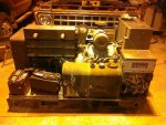
First of all, I thank you all on this forum for all the information I have learned about the MEP units. This is my first post but I have devoured tons of information and you have answered almost all of my questions. I bought the MEP at a farm auction which had been sitting in a barn for a number of years. The gentleman who owned wired it to his house but smoked his TV so it was pushed into the corner until he died. Of course I learned this after I was the proud new owner. I probably made some mistakes but I will tell you my story and wrap up with a couple of questions. Knowing me, this will be long…
After sealing the last bid and doing a closer inspection of my pride and joy I realized the re-connection switch was locked into the 3phase position. Maybe this explained the smoking TV… More about that later. The fuel tank had about 8-9 gallons and was really bad goo. I drained it and removed the tank. I pulled the fuel gauge assembly but the refill switch assembly wouldn’t budge so I left well enough alone. To clean the tank I used lye (sodium hydroxide) it does a good job of cutting organic growth. I suspect it would’t be good for the cork float which is why I pulled it. I have some red devil lye in a jar but had a half can of oven cleaner which is the same stuff so I squirted the full can into the tank. If you try this be aware not to breath any or get it into your eyes. It will also remove paint so I was careful not to get any on the outside of the tank. After sloshing it around a while I used my pressure washer in the open holes and it really came out nice and clean. It’s probably not so nice on the other side of the baffle but I will keep an eye on the fuel condition. I flushed the fuel lines, replaced the fuel filters, engine oil and filter.
Next, I worked on the re-connection switch. Most of what I read about was to flood it with WD-40, switch to the position for your application and leave it. I wanted it to work as intended. I can see using the 3-phase and 240v positions. I removed the front cover and top cover from the AC box. I did not disconnect any wires but did unbolt the terminal board to move it up and out of the way which gave better access to the switch. Removed the knob and the small leverage shaft which threads into the side main switch shaft. Removed the mounting bolts from the front and rear of the switch. (I did this when the tank was removed so access to the rear bolts was not a problem.) With all the wires attached, the switch is really a bear to move but I was able to push the rear of the switch down and toward the back of the box. This allowed the switch shaft to move free from the hole. I removed the front cover and studied how the switch works. Now I understand why the switch was stuck. I was worried the terminals welded themselves together but not the case. To lubricate the switch I made sure it was engaged in the 3phase position this helped hold the terminal lugs into position. I removed the next set of nuts from the long bolts holding the switch together. Using a can of silicon dielectric spray with applicator straw and my knife blade I carefully separated the switch segments just wide enough for the straw and flushed silicon into each section. Careful not to disturb too much and lubricating each section. When bolting things back together I was careful to make sure the segments sandwiched back together correctly. A couple of lugs did move a little and had to be adjusted so the plastic discs would come back together. I cleaned and lubricated the switch actuating springs with WD40 and spray lithium grease. After putting it all back together the switch works perfectly. With much less resistance.
After re-installing the tank I was able to get the engine running, it smoked and belched itself to life! It built up good oil pressure and sounded good. Brought it up to 60hz immediately but the output voltage on the 120v circuit was around 170v which equals a smoking TV! I did some reading and troubleshooting. I pulled the VR board and tested the output transistor as well as Q1 and Q2, all the diodes, resistors, etc. Nothing seems to be a problem except R15 was set at the far end of the setting; center terminal to one side was 2k ohms, center to the other side was 0 ohms. I haven’t been able to work in the unit since finding this, could this cause the VR from not regulating to 120v? The voltage adjust rheostat does nothing.
I assume I need set up the calibration circuit from the TM for the board. I wasn’t able to find any comments on here on the procedure, anything to look out for?
I have other questions but this is longer than I like so my other questions will wait.
Thank you all!
Jason


