• Steel Soldiers now has a few new forums, read more about it at: New Munitions Forums!

  • Microsoft MSN, Live, Hotmail, Outlook email users may not be receiving emails. We are working to resolve this issue. Please add support@steelsoldiers.com to your trusted contacts.

MEP 003A, Engine Runs, But No Generator Output

Floydla1

New member
26
16
3
Location
Mobile, Alabama
Hello All,

Brand new to the forum. Last month I got an MEP 003A off ebay that was guaranteed to work. It didn't. The cost to return the unit od prohibitive. So it is no my problem.

I running down the diagnostic found on page 2-9 of TM5-6115-585-34 while praying that this is not an open winding. I installed a new voltage regulator today, but it did not fix the problem. When running on 1-phase / 220V, I get 562mV between L1 and L3 and 263mV from each to ground. I get the same 256mV on the convenience receptacles.

Using the procedure in paragraph 8.2 of the same TM, I checked two of the exciter diodes (the ones that I can get to). Resistance is 1.3M-ohm and 1.2M-ohm respectively. However both diodes tested open when I reversed the leads. I found two stores that listed the Onan 358-0037 and 358-0024 respectively, and ordered the diodes. However, both stores are reporting that these part numbers are on back-order status (not a good sign). If someone has a cross-referenced part number for these, along with 1N4246, I would appreciate it.

For me the next step is to check generator rotor flashing circuit. In particular, the bridge rectifier (diodes 1N4246). If anyone is willing to work with me on a solution, I am grateful.

Service
NPN
Description
Mfg. / Part Nbr.
TM Ref.
Figure / Nbr.
Qty

Tot Qty
Bridge Rectifier
5961-00-914-9740
Semiconductor Device, Diode
JAN1N4246
TM5-6115-585-24P
15
6
15
Voltage Reg.
5961-00-914-9740
5961-00-900-0064
Semiconductor device, Diode
1N4246
JAN1N4246
TM5-6115-585-24P

7
13
Generator Rotor
5961-01-050-7048
Semiconductor Device, Diode
72-5273-2
ST Semicon S6248R
Onan 358-0037
TM5-6115-585-24P
26 / 27
3
3
Generator Rotor
5961-01-054-4151
Semiconductor Device, Diode
72-5273-1
ST Semicon S6248
Onan 358-0024
TM5-6115-585-24P
26 / 28
3
3
 

Triple Jim

Well-known member
1,375
287
83
Location
North Carolina
Henry, here's one thread I was telling you about. It has information about the rotating diodes. Mouser currently has both the 1N1206A and the 1N1206RA in stock at about $6 each. I recommend testing yours first with a meter that has a diode test function though, since it's quite possible that's not your problem.

https://www.steelsoldiers.com/showthread.php?170222-MEP-002a-Generator-Diodes

In case testing reveals a problem with the 1N4246 diode(s), that one is just a 400 volt 1 amp diode. I'd use 1N4005 (or 1N4006, 1N4007), which will work exactly as well, and are dirt cheap.
 
Last edited:

Floydla1

New member
26
16
3
Location
Mobile, Alabama
Hello TripleJim,

Thank you again for the Mouser part numbers -- you saved me money and time. The other sources were more expensive and were on backorder. Also thank you for a more detail on diode testing than is in the TM.
 

Chainbreaker

Well-known member
1,796
1,992
113
Location
Oregon
You should also try exercising the "AC Output Reconnection Switch" a few times, its the one next to the Circuit Breaker. That switch's contacts can sometimes become intermittent when left in one position. One of my units occasionally does not provide output unless I exercise that switch. Eventually I plan open the box and use some contact cleaner to improve its contact reliability.
 

Floydla1

New member
26
16
3
Location
Mobile, Alabama
To Chainbreaker: I noted on receipt of the unit that this switch was resistant to turning. I'll exercise the switch per your recommendation. I failed to mention that I am not getting power at the control box -- would this switch effect this as well?

To Buyfank: I performed the check per the TM5-6115-585-34 (see below). Based on the instructions, the first two diodes tested passed. An internet search turned up a FLUKE method which involves inducing voltage.

"Disconnect each diode (42) by removing nuts and washers (40 and 41).(c) Use an ohmmeter to measure the resistance between the terminal end and the threaded base (heat sink) end of the diode. Reverse ohmmeter leads and repeat the resistance measurement. A diode in good condition will have a very high resistance for one measurement and a resistance near zero when ohmmeter probes are reversed. Failure to obtain these two extremes in resistance measurement indicates a defective diode that should be removed and replaced."
 

Triple Jim

Well-known member
1,375
287
83
Location
North Carolina
As I mentioned in my email, measuring the resistance of a diode with an ohm meter is not likely to give you a good result. You need to use a meter with a diode test function or you need to put a small current through the diode and measure its voltage drop.

Years ago, a lot of meters used a high enough voltage when measuring resistance that you could use them for checking diodes, but most meters today don't.
 

profo

Active member
428
73
28
Location
jeanerette,la
Hello All,

Brand new to the forum. Last month I got an MEP 003A off ebay that was guaranteed to work. It didn't. The cost to return the unit od prohibitive. So it is no my problem.

I running down the diagnostic found on page 2-9 of TM5-6115-585-34 while praying that this is not an open winding. I installed a new voltage regulator today, but it did not fix the problem. When running on 1-phase / 220V, I get 562mV between L1 and L3 and 263mV from each to ground. I get the same 256mV on the convenience receptacles.

Using the procedure in paragraph 8.2 of the same TM, I checked two of the exciter diodes (the ones that I can get to). Resistance is 1.3M-ohm and 1.2M-ohm respectively. However both diodes tested open when I reversed the leads. I found two stores that listed the Onan 358-0037 and 358-0024 respectively, and ordered the diodes. However, both stores are reporting that these part numbers are on back-order status (not a good sign). If someone has a cross-referenced part number for these, along with 1N4246, I would appreciate it.

For me the next step is to check generator rotor flashing circuit. In particular, the bridge rectifier (diodes 1N4246). If anyone is willing to work with me on a solution, I am grateful.

ServiceNPNDescriptionMfg. / Part Nbr.TM Ref.Figure / Nbr.Qty
Tot Qty
Bridge Rectifier5961-00-914-9740Semiconductor Device, DiodeJAN1N4246TM5-6115-585-24P15615
Voltage Reg.5961-00-914-9740
5961-00-900-0064
Semiconductor device, Diode1N4246
JAN1N4246
TM5-6115-585-24P713
Generator Rotor5961-01-050-7048Semiconductor Device, Diode72-5273-2
ST Semicon S6248R
Onan 358-0037
TM5-6115-585-24P26 / 2733
Generator Rotor5961-01-054-4151Semiconductor Device, Diode72-5273-1
ST Semicon S6248
Onan 358-0024
TM5-6115-585-24P26 / 2833

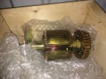
If you need I got complete MEP003 rotors with the diodes and bearings new , I need to get rid of, got over ten and want to quit tripping on them Ill sell for 100 bucks!

Martymep 003 rotor.jpg
 

profo

Active member
428
73
28
Location
jeanerette,la
Sorry double post!


Hello All,

Brand new to the forum. Last month I got an MEP 003A off ebay that was guaranteed to work. It didn't. The cost to return the unit od prohibitive. So it is no my problem.

I running down the diagnostic found on page 2-9 of TM5-6115-585-34 while praying that this is not an open winding. I installed a new voltage regulator today, but it did not fix the problem. When running on 1-phase / 220V, I get 562mV between L1 and L3 and 263mV from each to ground. I get the same 256mV on the convenience receptacles.

Using the procedure in paragraph 8.2 of the same TM, I checked two of the exciter diodes (the ones that I can get to). Resistance is 1.3M-ohm and 1.2M-ohm respectively. However both diodes tested open when I reversed the leads. I found two stores that listed the Onan 358-0037 and 358-0024 respectively, and ordered the diodes. However, both stores are reporting that these part numbers are on back-order status (not a good sign). If someone has a cross-referenced part number for these, along with 1N4246, I would appreciate it.

For me the next step is to check generator rotor flashing circuit. In particular, the bridge rectifier (diodes 1N4246). If anyone is willing to work with me on a solution, I am grateful.

ServiceNPNDescriptionMfg. / Part Nbr.TM Ref.Figure / Nbr.QtyTot Qty
Bridge Rectifier5961-00-914-9740Semiconductor Device, DiodeJAN1N4246TM5-6115-585-24P15615
Voltage Reg.5961-00-914-9740
5961-00-900-0064
Semiconductor device, Diode1N4246
JAN1N4246
TM5-6115-585-24P713
Generator Rotor5961-01-050-7048Semiconductor Device, Diode72-5273-2
ST Semicon S6248R
Onan 358-0037
TM5-6115-585-24P26 / 2733
Generator Rotor5961-01-054-4151Semiconductor Device, Diode72-5273-1
ST Semicon S6248
Onan 358-0024
TM5-6115-585-24P26 / 2833

If you need I got complete MEP003 rotors with the diodes and bearings new , I need to get rid of, got over ten and want to quit tripping on them Ill sell for 100 bucks!

MartyView attachment 744204
 

skidunits4you

Member
Steel Soldiers Supporter
123
1
18
Location
Washington NC
Just a quick question when you start the unit are you holding to start switch until the volt meter jumps to 120 volts and cycle meter jumps up to 60. these units require excitement by holding that switch until it starts generating power.
 

Chainbreaker

Well-known member
1,796
1,992
113
Location
Oregon
To Chainbreaker: I noted on receipt of the unit that this switch was resistant to turning. I'll exercise the switch per your recommendation. I failed to mention that I am not getting power at the control box -- would this switch effect this as well?...
So, you are saying that you are not getting 24 VDC to the control box as well as not getting AC voltage at the output load terminals in the AC distribution box. If so, that indicates more than likely your not generating any power from the Gen Head. So the advice you getting here regarding the rotating diodes and excitation voltage are more relevant. Proceed in that direction first.

FWIW, the AC Voltage Reconnection switch is often hard to turn if it has not been switched in a while. Caution! NEVER attempt to turn the AC Reconnection Switch with the genset running. I had to work mine left & right with increasing pressure each time I attempted to switch it to another setting. Eventually it loosened up and I was able to exercise it much easier. If you were to peek inside the Reconnection box that houses the switch (take the lower side panel off just below the AC load terminals) you can see what a behemoth it is. If it refuses to turn with a little persuasion don't force it too hard or you might break it or the switch knob itself. Here is a link to a thread describing how to free up a stuck AC Reconnection Switch if you should ever need to do that:

https://www.steelsoldiers.com/showthread.php?82455-Mep-002A-AC-Reconnection-Switch
 
Last edited:

Floydla1

New member
26
16
3
Location
Mobile, Alabama
MEP 003A, Engine Runs, No Voltage

The MEP 003a I have was refurbished by JimC and includes a replacement of the analog gauges with digital. I do hold the switch at start for at least 10 seconds. At no time do the gauges show anything. Since I replaced the VR board, the main suspects are the generator itself or the flashing circuit. A check of three of the six diodes on the rotor using a Fluke 1587 indicates they are ok (see below). However, getting to the A-4 board with the diode matrix is not going to be easy.

A post from a prior thread regarding this issue seems to be a logical next step:

"Pull the cover from the side of the AC Reconnection box. The terminal block in question is literally just inside the box and probably the easiest area to work with.
Locate position 5 and 6 on that terminal block. Disconnect the upper wire at 5 and 6. These go up to the VR circuit board. Wire up a 12 volt battery in their
place, being careful to observe the correct polarity spelled out in the -34. I like to connect the wires first so I am sure not to short anything out. Once I
have the wires attached to the terminal block, I then connect the battery, followed by starting the generator. If you do not get power generation then,
your problem is below that level and probably somewhere within the AC Reconnection box. In that case, check the diode matrix at A4 carefully. If you
do get power generation, your problem is one of the circuits on the VR circuit board, since that is the only part being bypassed for this test. "


If someone has experience using an external power source, I would like to know how you did this.


From
<https://www.steelsoldiers.com/showt...Z-reading-on-meters/page4&highlight=glow+plug>

Fluke 1587 Diode Test.jpg
 
Last edited:

profo

Active member
428
73
28
Location
jeanerette,la
Also a quick and down and dirty check can be done by remove the small two pin connector coming from the gen head going to control box and while running touch a 9 volt battery to the two pins on gen side , voltage will jump up , this flashes the gen and checks all the generator parts at same time , should put a 2 amp fuse in inline and use alligator clips to test!
 

massey

Member
72
7
8
Location
Marshall Va
"The MEP 003a I have was refurbished by JimC and includes a replacement of the analog gauges with digital. I do hold the switch at start for at least 10 seconds. At no time do the gauges show anything."

I have the same gauges and they also don't display until I flick the main ac breaker on.


Floydla1

New member
26
16
3
Location
Mobile, Alabama
This afternoon I tested profo's 9V flash test (see post #13). It worked.
Thanks to all that contributed. I am still low on the learning curve, but without your suggestions I would still be in the weeds.
Best regards.
WP_20181009_15_21_31_Pro.jpg
 

Triple Jim

Well-known member
1,375
287
83
Location
North Carolina
I'm glad it's working, but I have to wonder why the built-in flashing circuit didn't work when the 9v battery did. It might be worth checking out that circuit to make sure it's working for next time.
 

profo

Active member
428
73
28
Location
jeanerette,la
If you cant figure the flash part you can take a ten ohm 10 watt resistor and thru a relay tie it into the same circuit then on input side you tie that to the small wire on starter what this does is apply a small voltage to the field while cranking and its usually enough to flash the gen everytime youbcrank it! The relay disconnects the flield from starter so it doesnt interfere once its runing.
 
Top
AdBlock Detected

We get it, advertisements are annoying!

Sure, ad-blocking software does a great job at blocking ads, but it also blocks useful features of our website like our supporting vendors. Their ads help keep Steel Soldiers going. Please consider disabling your ad blockers for the site. Thanks!

I've Disabled AdBlock
No Thanks