• Steel Soldiers now has a few new forums, read more about it at: New Munitions Forums!

  • Microsoft MSN, Live, Hotmail, Outlook email users may not be receiving emails. We are working to resolve this issue. Please add support@steelsoldiers.com to your trusted contacts.

MEP-005a single phase conversion gauge question

shanekarl

Member
55
57
18
Location
Fort Worth, Texas - USA
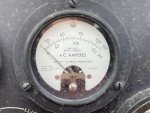
My mep-005a has been converted to single phase and my A.C. Amperes gauge is not working. Can someone confirm if this gauge will work when converted to single phase? I have read both that it will and it will not.

I found a replacement gauge but before i order it i just want to be sure it should still work in single phase.

Thanks
 

Ray70

Well-known member
2,595
5,914
113
Location
West greenwich/RI
The set Shane is talking about came from me. The single phase conversion was done before load testing, so I don't know if the Amp gage worked prior.
This is the 3rd 005A that I have had and none of them had Amp gages ( #6 in the TM ) that had a reading ( all tested after the conversion ) but all 3 had %load gages ( #4 in TM ) working correctly. I think I was mistakenly under the impression that the Amp gage ( #6 ) was only used when 1 or more units were hooked in parallel.
The conversion was done according to Matt Verley's video.
All 3 machines were set from the beginning with the A/V switch in the L1-L3 setting to display 240V on the gage.
Before Shane buys a gage, I think he should be able to test the circuit with a DMM.
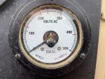
Shane, can you post a picture of the face of both gages, so we can see the full swing current rating in fine print near the 4:00 position on both gages?
Should say something like XX mA DC?
And does 1 gage say % Power and the other say % Current?
 

shanekarl

Member
55
57
18
Location
Fort Worth, Texas - USA
Hey Ray,

Photos of both gauges are below. I have not tested the gage with a MM but i should have connectivity across the posts, ill test that later today.

I did order a new gauge, it was only $25 on an identical NOS gage so I am willing to risk that.

Here is a link to what i ordered... The guy was asking $50 but i did a best offer of $25 and he accepted.


IMG_6944.jpg

IMG_6945.jpg
 
Last edited:

Ray70

Well-known member
2,595
5,914
113
Location
West greenwich/RI
If you want to test the circuit you should be able to remove the wires from the back of the gage and set your meter for AC amps. ( or milli. amps )
( Plug the red lead into the appropriate spot on the meter )
with the machine at full load you should have 1 amp flowing between the gage wires. At 50% load you should have .5A AC

Looking at some videos on line it looks like that gage ( % current ) should move in unison with the % Power meter to it's left.
I guess my question for the group is: In a stand alone configuration, what exactly is the purpose of having 2 gages that are both apparently measuring percentage of output? Guess I'm not quite understanding why the 004, 005 and 006 have 2 gages as compared to the single load meters on the smaller machines.
 

Ray70

Well-known member
2,595
5,914
113
Location
West greenwich/RI
Ah ha! Scoobyshep, you may have just solved it!

Looking at the A/V switch it appears that Amps only register when set to L1-L0, L2-L0 or L3-L0 not when set to L1-L3 or any other line to line setting.

Shane, turn the A/V switch 1 click to the right to the L1-L0 setting and retest.
I think the reason I have never seen that gage work after a single phase conversion is that I always set the A/V switch to L1-L3 to observe 240V on the volt meter. According to the white circular lines on the gage panel around the switch, you can not register amps in that position.
 

Scoobyshep

Well-known member
1,137
1,511
113
Location
Florida
Ah ha! Scoobyshep, you may have just solved it!

Looking at the A/V switch it appears that Amps only register when set to L1-L0, L2-L0 or L3-L0 not when set to L1-L3 or any other line to line setting.

Shane, turn the A/V switch 1 click to the right to the L1-L0 setting and retest.
I think the reason I have never seen that gage work after a single phase conversion is that I always set the A/V switch to L1-L3 to observe 240V on the volt meter. According to the white circular lines on the gage panel around the switch, you can not register amps in that position.
That would do it, Gotta look at the label ring marked Amps. Id be lying if I said I never did that one myself.
 

shanekarl

Member
55
57
18
Location
Fort Worth, Texas - USA
That would do it, Gotta look at the label ring marked Amps. Id be lying if I said I never did that one myself.
You guys are spot on. When i turn to L1, L2, L3 the amps gauge jumps into action! Does not really matter which of the positions i use as its converted to 1 phase all positions read the total amp usage. Totally had no idea thats what that means or even that I could turn that dial so very productive day!

Thanks both of you very much!
 

Scoobyshep

Well-known member
1,137
1,511
113
Location
Florida
The positions do matter. If this was done exactly as I think it is L2 won't mean much to you L1 and L3 both represent the current usage and depending on how your balance one may be higher than the other

Sent from my SM-G973U using Tapatalk
 

shanekarl

Member
55
57
18
Location
Fort Worth, Texas - USA
The positions do matter. If this was done exactly as I think it is L2 won't mean much to you L1 and L3 both represent the current usage and depending on how your balance one may be higher than the other

Sent from my SM-G973U using Tapatalk
When I move the dial to L1-L0 or L3-L0 the AC Amperes gauge show 50 amps on either selection. The generator was loaded to 12kw (from a a427a load bank) at 239volts. That is a total of 50amps not 50amps per leg so i think the gauge at l1 or l3 is showing my total usage not usage per leg - however usage per leg would be useful as you mentioned see how balanced or unbalanced the load is.
 

Scoobyshep

Well-known member
1,137
1,511
113
Location
Florida
Current between l3 and l0. And current between l0 and l1. Since youre running 240 volt on the load bank very little (if any) current is actually going to chassis on l0 so yes they should match

Sent from my SM-G973U using Tapatalk
 
Top