• Steel Soldiers now has a few new forums, read more about it at: New Munitions Forums!

  • Microsoft MSN, Live, Hotmail, Outlook email users may not be receiving emails. We are working to resolve this issue. Please add support@steelsoldiers.com to your trusted contacts.

MEP 804a under voltage after start up

SQF

New member
25
2
3
Location
Chelsea, Michigan
Novice gen set owner. I have an 804a with 794 hours that has run flawlessly since I bought it with 30 hours. Just today it started faulting under voltage after releasing S1 regardless of how long I hold it on start. After releasing S1 I lose all voltage and the fault light comes on. There is also a noticeable drop in rpm. If I rotate S1 back to start it shuts down on an over speed fault. I am in the field with access to my phone but no access to the TM. I have a Libby voltage regulator and the fuse to the left side of it. Can anyone help me sort this out. I have a volt meter on my truck.

thanks
 

kloppk

Well-known member
Steel Soldiers Supporter
2,145
3,526
113
Location
Pepperell, Massachusetts
TM Test Procedure for Libby VR..


4-1.1 Testing (AC Voltage Regulator, P/N 01-21501-1, for MEP-804A/MEP-804B).
a. Shut down generator set.
b. Open output box access door.
c. Note position of voltage reconnection terminal board and set FREQUENCY SELECT switch to 60
Hz position.
d. Start generator set and turn VOLTAGE adjust potentiometer to ensure adjustment ranges on
Table 4-1 are met, depending on position of voltage reconnection terminal board.
e. Shut down generator set.
f. If no voltage or low voltage was indicated or voltage adjustment range could not be achieved,
perform the following steps. Otherwise, AC voltage regulator (2, Figure 4-1) is serviceable.
g. Disconnect wire 141A from terminal 1 of AC voltage regulator.
h. Set multimeter for DC volts and connect positive lead to wire 141A. Connect negative lead of
multimeter to terminal 3 of AC voltage regulator. Start generator set and operate at rated
frequency. Move and hold MASTER SWITCH in START position. Multimeter should indicate
between 4 and 12 VDC.
i. Shut down generator set. Isolate wire 141A.
j. Set multimeter for AC volts and connect to terminals 10 and 11 of AC voltage regulator. Start
generator set and operate at rated frequency. Move and hold MASTER SWITCH in START
position. Multimeter should indicate 210 to 280 VAC.
k. Shut down generator set.
l. Disconnect wire 137A from terminal 5 of AC voltage regulator. Set multimeter for ohms and
connect positive lead to wire 137A and negative lead to terminal 4 of AC voltage regulator. Move
VOLTAGE adjust potentiometer to full counterclockwise (CCW) position. Multimeter should
indicate approximately 3,000 ohms with FREQUENCY SELECT switch in 60 Hz position, and
approximately 0 ohms with FREQUENCY SELECT switch in 50 Hz position. Move VOLTAGE
adjust potentiometer slowly clockwise (CW) while observing multimeter. Multimeter should
increase smoothly to approximately 10,000 ohms.
m. If steps h, j, and l are as indicated above, AC voltage regulator is defective and must be replaced.
n. Connect all wires previously disconnected. Close output box access door.
 

SQF

New member
25
2
3
Location
Chelsea, Michigan
After mulling over many of Guy's posts, I have a suspicion that S1 is bad. I have the #1 or #2 style switch, not the bakelite style. It is "sticky" and late in the day was intermittently not even closing the start circuit on the generator. I have looked through Guy's postings of the complete TM's for the 804a and I can't seem to find the testing procedure for S1. Can you point me in the right direction?

Second, I have a fully functioning MEP803, could I take the S1 out of it and put it in my 804 without a problem? I thought that might be an easy way to test my theory.


Thanks for the help
 

kloppk

Well-known member
Steel Soldiers Supporter
2,145
3,526
113
Location
Pepperell, Massachusetts
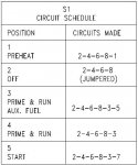
Here is the 804's S1 Circuit Schedule for reference
804A S1 Circuit Schedule.JPG

Basically S1-2,4,6,8 should have 24 volts on them all the time (Dead Crank in Normal and EPO switch pulled out)
In PreHeat S1-1 should have 24 volts on it
in Prime/Run Aux Fuel S1-3 & S1-5 should have 24 volts on them
in Prime/Run S1-3 should have 24 volts on it
in Start S1-3, S1-1, & S1-7 should have 24 volts on them. (S1-1 because of the diode on S1)
 

SQF

New member
25
2
3
Location
Chelsea, Michigan
Well guys, I am at a loss. I replaced s1 with one off another gen set. Tested the VR and exciter stator and everything is within the spec'd ranges. I don't know where to go from here. Gen set starts up and produces voltage in the start position, upon returning to prime/run it throttles down very slightly and stops producing voltage. Any suggestions?
 

SQF

New member
25
2
3
Location
Chelsea, Michigan
Ok guys, new VR from Kloppk and now I have a new problem. When I release S1, I no longer get an undervoltage fault, but the engine rpm increases slightly and then it shuts down on an over speed fault. Kloppk suggested testing the A5 but I don't think I have enough hands to do it by myself. Seems odd that I had an undervoltage problem prior to the new VR and now I have an overspeed fault. I tested the MPU and I am getting 2.8VAC on start but only 748ohms. The spec is 8-900. Is that enough to cause my problem?
 

Guyfang

Moderator
Staff member
Moderator
16,766
24,072
113
Location
Burgkunstadt, Germany
I tested the MPU and I am getting 2.8VAC on start but only 748ohms. The spec is 8-900. Is that enough to cause my problem?

This is NOT how you test the MPU. Test the MPU using the S10. You don't want to start the set. Crank it over with the S10, to see if you get 2.8 VAC, and it STAYS at 2.8 VAC.

Are you using a good DMM? Is it reading right? Ohms were measured at the MPU? Or did you measure at the A5?

When it shuts down, do you get any idiot lights?
 

SQF

New member
25
2
3
Location
Chelsea, Michigan
I tested the MPU and I am getting 2.8VAC on start but only 748ohms. The spec is 8-900. Is that enough to cause my problem?

This is NOT how you test the MPU. Test the MPU using the S10. You don't want to start the set. Crank it over with the S10, to see if you get 2.8 VAC, and it STAYS at 2.8 VAC.

Are you using a good DMM? Is it reading right? Ohms were measured at the MPU? Or did you measure at the A5?

When it shuts down, do you get any idiot lights?
I'm sorry Guy, I should have been more clear. Yes, I tested the MPU at the MPU using s10, it reads 2.8VAC and stays at 2.8. I am using a nice Greenlee DMM. When it shuts down I get and overspeed idiot light.

Thanks for helping
 

SQF

New member
25
2
3
Location
Chelsea, Michigan
Is the A5 correctly hooked up?

Is the set in 60 hertz mode?

Is TB1 set up correctly. For the voltage you want?
So, I haven't ever touched A5 and it ran 750+ hours without a problem. I am making the assumption that it is still correctly hooked up. When you say "is it set in the 60hz mode," do you mean the A5? If so, I am not aware of how to change that mode, nor would I know why anything was changed. If you are referring to the 50hz/60hz switch, then yes it is in the 60hz position.

I don't believe anything on TB1 has been changed from when it was running without issue, but I will confirm when I get back to it shortly. I came back to the shop to read more in the TM and use my computer. It's super hard in the field using my phone...

Thanks
 

Guyfang

Moderator
Staff member
Moderator
16,766
24,072
113
Location
Burgkunstadt, Germany
Yes, I meant the 50/60 switch, S19?

If you have not changed the TB1 and it ran right before, then don't worry about it.

Also, try pulling the plug out of the fault indicator again. Then try and start it.
 

SQF

New member
25
2
3
Location
Chelsea, Michigan
Yes, I meant the 50/60 switch, S19?

If you have not changed the TB1 and it ran right before, then don't worry about it.

Also, try pulling the plug out of the fault indicator again. Then try and start it.
You got it… unplugging said the fault indicator solves it. It runs like it should. Does that mean the fault indicator is bad?
 

SQF

New member
25
2
3
Location
Chelsea, Michigan
You got it… unplugging said the fault indicator solves it. It runs like it should. Does that mean the fault indicator is bad?
I should clarify, not sure if this is normal but I step up to run L1&L2 and I’m getting 133vac on one leg and 129vac on the other but 236vac across both. Seems normal for 240 but high on the 120 legs.
Guy correct me if I’m in error but the 803 and 804 run a different fault board correct? Thought I read that from you in all my research for this issue. I have an 803 at the shop I could borrow from if they are the same.
Other than voltage mentioned above the only other thing is I have no reading on M8, but M9 is reading. Otherwise it appears to run normal.
 

Guyfang

Moderator
Staff member
Moderator
16,766
24,072
113
Location
Burgkunstadt, Germany
Guy correct me if I’m in error but the 803 and 804 run a different fault board correct? Correct.

If M9 is reading, then you have a load? How much is it reading?

M8. Is your S6 in the proper position?
 
Top
AdBlock Detected

We get it, advertisements are annoying!

Sure, ad-blocking software does a great job at blocking ads, but it also blocks useful features of our website like our supporting vendors. Their ads help keep Steel Soldiers going. Please consider disabling your ad blockers for the site. Thanks!

I've Disabled AdBlock
No Thanks