• Steel Soldiers now has a few new forums, read more about it at: New Munitions Forums!

  • Microsoft MSN, Live, Hotmail, Outlook email users may not be receiving emails. We are working to resolve this issue. Please add support@steelsoldiers.com to your trusted contacts.

MEP-804B no output

PilotColt

New member
9
0
1
Location
South East LA
I have an MEP-804B that was suppose to work but has no output. The engine cranks and runs really well but no voltage on any of the 3 lugs. Both freq and volt potentiometers have no real affect on the meter, however you can hear a rpm pick up while turning the freq. Also the convenience receptacle is not working (likely part of same issue). My dad purchased this and I am trying to help him fix it but not sure where to start with the troubleshooting.

Drive video link:
 

Attachments

kloppk

Well-known member
Steel Soldiers Supporter
2,114
3,469
113
Location
Pepperell, Massachusetts
If you haven't already downloaded the Maintenance and Repair TM 9-6115-643-24 from the TM download section of this forum do that for starters.

From your video it appears there is an issue with the AC Voltage Regulation system.
When you started the set and had S1 in the START position after it came up to speed you had AC Voltage on the AC Voltmeter and Frequency on the Freq meter. When you released S1 back to Prime/Run both meters went to zero.

When the set is started, and you still have S1 in START the set flashes the generator head to kick off the AC generation process. This is NOT done by the AC Voltage Regulator. When you release S1 back to Prime/Run the AC Voltage Regulator is supposed to step in and maintain AC Voltage output.

From those indications it tells me there is a problem with the AC Voltage Regulation system. It's comprised of transformer T1, Resistor R16, the front panel potentiometer and the AC Voltage Regulator assembly.

I suggest performing the AC Voltage Regulator test per the -24 TM and post of your findings for each test step.

**Note the 804B sets were built with two different AC Voltage Regulation systems. One made by LIBBY and the other by Technology Research Corp (TRC).
The systems use different AC Voltage Regulators, R16's, T1's and front panel potentiometers for each system.
Be sure not to mix parts from one system with the other. Bad things can happen!

The -24 TM calls out different AC Voltage Regulator tests depending on if it's a LIBBY or TRC system.
 
Last edited:

PilotColt

New member
9
0
1
Location
South East LA
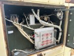
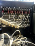
Thank you for all of the helpful information. I opened up the top of the control box and it is TRC regulator listed PN: 30554 and 19870. I am currently looking for the testing procedure and will let you know what I find. There is also tube fuse on the rear wall on the left side of the regulator that does not have any markings for amperage but is blown / no continuity (roughly 3/8 diameter and 1.5" long).
 

kloppk

Well-known member
Steel Soldiers Supporter
2,114
3,469
113
Location
Pepperell, Massachusetts
The fuse is a KTK-3 fuse. 3 amp Fast Acting Fuse.
If the fuse is blown it's generally not a good sign.
That fuse is there to protect the gen heads Static Exciter should the AC Voltage Regulator put out way too much voltage to it.
Without that fuse the AC Voltage Regulator has no control on the generator AC output voltage.
Try replacing the fuse with a good one. If it blows again, it's likely the AC Voltage Regulator has failed.
 

Guyfang

Moderator
Staff member
Moderator
16,558
23,605
113
Location
Burgkunstadt, Germany
If a new fuse corrects the problem, don't forget to have a spare. The fuse can also blow if someone holds the S1 in the start position TOO long. By too long I mean longer than 20-30 seconds.
 

PilotColt

New member
9
0
1
Location
South East LA
Replaced the fuse and video attached. The frequency and voltage are now coming up and both adjustable with potentiometer knobs, it seems to easily flag "overspeed" and shut off with red indicator. I still am getting 0 voltage to the output cable box lugs and only 4.5 volts on the courtesy receptacle. I tested the regulator as per 4.1.2 and h (term 1 wire to term 3 got 3.8-8 volts) j (term 10 and term 11 147.5 ac) L (ohms didn't read on meter, but adjust on unit with turning).


kloppk

Well-known member
Steel Soldiers Supporter
2,114
3,469
113
Location
Pepperell, Massachusetts
For AC voltage to get to the lugs you need to close the AC Circuit Interrupter (contactor).
I don't see the AC Circuit Interrupter lamp on, so it appears the contactor is still open.
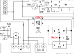
Lack of voltage to the outlet may be due to the GFCI being tripped or the circuit breaker on the side of the GFCI being tripped.

Is your hand-held meter capable of measuring AC Frequency? If so, hook it up to the two terminals on the front panel AC Voltmeter and check the frequency there and compare it to the front panel frequency gauge. The generators frequency measuring systems fail with some frequency (no pun intended).
 

PilotColt

New member
9
0
1
Location
South East LA
Got the contactor to close and do have voltage at all of the lugs. Still having an issue with the generator shutting down for overspeed warning. With both the freq and volt turned all the way down on the 50 hz switch side running reading 53 once you close the contactor and get a light 58 with the knob all the way down. On the 60 hz switch side 59 and 61 with the contactor closed if it doesn't immediately shut off when you hit the switch about 50/50 percent of time it works or its shuts the unit down. Borrowed a meter to check leads when it was working and they are close maybe .5-1.0 hz off with the unit reading to the high side over the meter.
 

PilotColt

New member
9
0
1
Location
South East LA
Have reset the overspeed switch several times. After starting and running the unit quite a bit, it appears to be operating and putting out power but still having a frequency issue or sensitivity. Sometimes on start up it will shut down for overspeed immediately and sometimes it will run. If you hold the S1 switch for more than 2-3 seconds it will overspeed. Anytime you open the AC Circuit contactor it pegs the frequency and overspeed. If you attempt to start it at anything above both knobs fully to the left it overspeed.

If you crank with both knobs all the way low and immediately release the S1 switch once it starts and give it 30 seconds to warm up and stabilize it will take contactor closing and put out to the lugs if you open the circuit interrupter with anything more than both knobs turned back all the way down it will overspeed and not continue running for cool down.
 

Attachments

jamawieb

Well-known member
1,434
549
113
Location
Ripley/TN
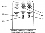
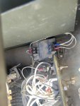
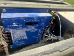
You're doing great. To adjust the set point for overspeed, look at the blue box on the back wall inside the control cubicle (behind gauges). At the top center you will see several adjustment pots. Look to the right and it says Overspeed, take a small flat head and turn it 90 degrees clockwise until it stops shutting down on you.
The board manual actually says to set the unit to 66 hertz and if it doesn't shut down, slowly turn the overspeed pot CCW until the unit shuts downs. That is how you're supposed to adjust it but yours is the opposite since its shutting down way before 66 hertz.
 

PilotColt

New member
9
0
1
Location
South East LA
Ok I will get on that next and report back. Need to go find a micro flat head. From what I can tell it seems to be kicking off over speed currently around 61-62
 

PilotColt

New member
9
0
1
Location
South East LA
Yes, they are awesome. It seems to be operating now. I appreciate all the help. I will have to build an output cable to load test now that it appears to be working. The only other issue that I am working on now is the courtesy outlet is not working. It is putting out 4.5 volt AC. The breaker is in but not sure it is working, also need to identify source power.
 

PilotColt

New member
9
0
1
Location
South East LA
There is power coming into but not out of the breaker for the outlet. PN:19990-2. I have been looking for one but they seem hard to find. Might for the time being remove it and install an 10amp inline fuse or similar breaker.

Is there some other component or control box the outlet runs through that is limiting it to 10 amps or could the system be wired for 15 or 20 amps?
 
Top
AdBlock Detected

We get it, advertisements are annoying!

Sure, ad-blocking software does a great job at blocking ads, but it also blocks useful features of our website like our supporting vendors. Their ads help keep Steel Soldiers going. Please consider disabling your ad blockers for the site. Thanks!

I've Disabled AdBlock
No Thanks