• Steel Soldiers now has a few new forums, read more about it at: New Munitions Forums!

  • Microsoft MSN, Live, Hotmail, Outlook email users may not be receiving emails. We are working to resolve this issue. Please add support@steelsoldiers.com to your trusted contacts.

MEP-831a GOVERNOR CONTROL assembly

Icon73

New member
Steel Soldiers Supporter
4
2
3
Location
Los Gatos, Ca
Hi Everyone,

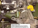
I am new to the forum. I recently picked up a MEP-831a they seem be be amazing machines. I got mine home and it is running but the Governor Control assembly seems to be in bad shape. I was wondering if anyone could help me out a little bit. The springs in my unit have been disconnected and sadly the documentation doesn't show exactly where I should connect some of the springs. Does anyone have a photo of what the back of the mechanical governor looks like. Details of where the springs connect please? i know that spring 5 connects to arm 6 and arm 7, but it is unclear to me which attachment points it should use as default. Any help, or a photo of the back or side your governor would be of great assistance. Thank you.

Mike
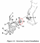
Fig4-2-spring5.PNGgovernor_front.PNG
 

kloppk

Well-known member
Steel Soldiers Supporter
2,145
3,526
113
Location
Pepperell, Massachusetts
Here is a picture with the mechanical governor plate tipped down for clarity.
Can be found here ---> Governor Adjustment Procedure
I see the top adjustment bolt on your set is missing the factory locking wire and lead seal. Usually means someone fiddled with that adjustment.
I can't tell from your picture if the lower adjustment bolts locking wire is missing too.
Governor Spring Hole.JPG
 
Last edited:

Mullaney

Well-known member
Steel Soldiers Supporter
Supporting Vendor
7,716
19,766
113
Location
Charlotte NC
Hi Everyone,

I am new to the forum. I recently picked up a MEP-831a they seem be be amazing machines. I got mine home and it is running but the Governor Control assembly seems to be in bad shape. I was wondering if anyone could help me out a little bit. The springs in my unit have been disconnected and sadly the documentation doesn't show exactly where I should connect some of the springs. Does anyone have a photo of what the back of the mechanical governor looks like. Details of where the springs connect please? i know that spring 5 connects to arm 6 and arm 7, but it is unclear to me which attachment points it should use as default. Any help, or a photo of the back or side your governor would be of great assistance. Thank you.

Mike
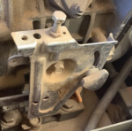
View attachment 895733View attachment 895734
.
Welcome to the Outfit!

Maybe you should consider some on-line docs.


Icon73

New member
Steel Soldiers Supporter
4
2
3
Location
Los Gatos, Ca
Kurt thanks for the photograph. My new controller already arrived, and once I get everything put into it's proper place I will install it. Very exciting.

Mullaney thanks for the links to the manuals.

I will likely get some time to work on the unit in the next day or two, and I will see about posting photos after I get everything back where it belongs. Thank you both for the help.

-Mike
 

Icon73

New member
Steel Soldiers Supporter
4
2
3
Location
Los Gatos, Ca
Wanted to update everyone on my progress. I cleaned up the inside of the cabinet. That was a job in itself. Seemed like a mix of oil and fuel and ultra fine sand. The unit is much easier to work on without all the grit and grime.

I changed the oil on the unit, I had no idea when the oil was last changed.
I reassembled the mechanical governor. Thank you for the help and the photos, and the documents.

I put 2 ATV batteries in series and made myself a shiny new 24 volt battery for the unit.

I noticed that there air cleaner assembly was completely absent. I found a replacement on ebay and it arrived.

I installed the KK digital speed controller after labeling the wires. i adjusted the electronic governor according to the instructions. One thread showing etc.

So the moment of truth arrived. I switched the unit from off to run and I immediately heard fans begin to spin. Pressed the switch to the next position and the diesel started. There was some white smoke, that quickly went away and the smoke turned black. Not unlike my MEP-531a produces when there is no load on the unit and it is cold.

So here is the set of questions:
It didn't seem like the engine came up to full speed, and I didn't see the electronic controller doing much. It wasn't moving as far as I could tell. I didn't see the 2 diodes on the controller light up. I need to do more trouble shooting there.

I put the switch into the off position and the engine kept running. So I moved the mechanical governor from run to stop and the unit kept running. I pushed the throttle arm all the way down with my fingers still the engine continued to run. I had remembered a video from youtube where the guy said to try pulling the compression release if the engine wouldn't shutoff, so I pulled the compression release and the engine shut off. Any guesses where I should begin to look to troubleshoot? I was going through the engine manual, and I didn't see this specific symptom in the trouble shooting guide. Diesel is new to me. I usually work on small gas engines, but ever since I bought my MEP-531a I have been excited about diesel gensets and the 831 seems like it is really nifty, but I need to work out the bugs.

Thanks in advance for any suggestions
Mike
 

kloppk

Well-known member
Steel Soldiers Supporter
2,145
3,526
113
Location
Pepperell, Massachusetts
...
So here is the set of questions:
It didn't seem like the engine came up to full speed, and I didn't see the electronic controller doing much. It wasn't moving as far as I could tell. I didn't see the 2 diodes on the controller light up. I need to do more trouble shooting there.
If the two LEDs on the controller are NOT illuminated it indicates the controller is not getting 24 volt power. This is usually due to the generator detecting a fault and dropping power to the controller. After starting it look to see if the tiny LED inside K12 (leftmost relay) is illuminated. If illuminated, it indicates there was a fault. Are any of the Fault Monitor lamp illuminated after you start it?

I put the switch into the off position and the engine kept running. So I moved the mechanical governor from run to stop and the unit kept running. I pushed the throttle arm all the way down with my fingers still the engine continued to run.
Do you mean the black throttle arm or the arm of the electronic actuatot?
 

Icon73

New member
Steel Soldiers Supporter
4
2
3
Location
Los Gatos, Ca
"If the two LEDs on the controller are NOT illuminated it indicates the controller is not getting 24 volt power. This is usually due to the generator detecting a fault and dropping power to the controller. Are any of the Fault Monitor lamp illuminated after you start it?"

There were not fault lamps lit other than the low oil pressure until the engine started and then it went out. I found another thread where you had helped trouble shoot another 831 and you had mentioned looking at the relay all the way on the left to see if it had a diode on. While there was no lamps on on the fault panel there was a green diode lit up on the relay on the left prior to starting. I need to read through the other thread and see about going through those trouble shooting steps.

" Do you mean the black throttle arm or the arm of the electronic actuatot? "

The black throttle arm. The arm of the electronic actuator has a shaft that sits in a ring on the black throttle arm. I did not push the electronic actuator arm. The Stop Run arm when I released the thumbscrew took off the spring tension. I thought that would have shut down the unit. It didn't. So I pushed down the black throttle arm with my fingers. This did not shut down the machine. I need to dig through the manuals and understand how the throttle linkage works. If you have any guesses where I should start based on your experience please let me know. Thanks!!

-Mike
 

kloppk

Well-known member
Steel Soldiers Supporter
2,145
3,526
113
Location
Pepperell, Massachusetts
Have you pressed the TEST button on the Fault Monitor to test all the lamps in the Fault Monitor.

If the LED inside K12 is illuminated but the Fault monitor doesn't have lamps illuminated it could mean there is a failure inside the Fault Monitor itself. They do fail. I've repairs a few of them in the past.

You could unplug the white plug from the back of the fault monitor to stop it from tripping the K12 fault relay.
You can start and run the set with it unplugged.
** However doing so prevents the fault monitor from shutting the set down due to any fault **
 
Top