• Steel Soldiers now has a few new forums, read more about it at: New Munitions Forums!

  • Microsoft MSN, Live, Hotmail, Outlook email users may not be receiving emails. We are working to resolve this issue. Please add support@steelsoldiers.com to your trusted contacts.

MEP802A overload tripping

Bassfishin114

Member
19
33
13
Location
Orlando Florida
I am fairly new to the military genset world but have spent countless hours on this site reading and have found so much valuable information. I have my Mep802a hooked up to my house as a back up generator. Today I did the first load test and it was going good. I turned the oven on and it was pulling around 20amps and showing about 60-70% load ( no other circuit connected). After a minute it tripped the overload. I retried this multiple times and got the same result. Have L1,L3 wired to hot, N to panel ground, and it is unbonded at the generator. I do not have a grounding rod or ground connected. Should that be done and would that cause this issue? When it tripped there was no amp increase or load increase indicated. I let it run for about an hour at 40% load with no issues. Unit is running about 62hz/245v without load and 61hz/242v under 60% load. Can anyone lead me in the right direction? I skimmed through the TS section of the manual but didn’t see anything really related.
 
Last edited:

Scoobyshep

Well-known member
1,134
1,508
113
Location
Florida
You absolutely should have the set grounded. In your case if you aren't switching the neutral, (which is most cases) leave the generator neutral-ground bond open and tie the generator chassis to the ground bar in your panel ( should be 4 wire. L1 L3 L0(neutral) and ground. As for premature tripping, I would check the actual current draw with a separate meter first.

Sent from my SM-S908U using Tapatalk
 

Bassfishin114

Member
19
33
13
Location
Orlando Florida
You absolutely should have the set grounded. In your case if you aren't switching the neutral, (which is most cases) leave the generator neutral-ground bond open and tie the generator chassis to the ground bar in your panel ( should be 4 wire. L1 L3 L0(neutral) and ground. As for premature tripping, I would check the actual current draw with a separate meter first.

Sent from my SM-S908U using Tapatalk
I had my amp clamp meter around 1 hot wire at the panel which is where I got my amp readings from. I will get the ground added.
 

Evvy Fesler

Well-known member
366
772
93
Location
Roxboro, North Carolina USA
Welcome!

I can help with terminology, if you don't mind?
L1, L3, should each be connected to you panel's L1, L2 respectively, typically black.
N should be connected to your panel's N, typically white
Genset selector, inside the control cube, should be in 240v, 1P mode

Grounded in electrical world means N, or neutral, typically white.
The spelling "ed" vs "ing" is special and actually means distinctive things.
Grounding means earth via the grounding electrode, typically bare copper and sometimes green.
Bonding means to make a solid connection between N, grounded and grounding at the first point of disconnect, i.e., the main panel. It is here that white wires are connected to bare copper (sometimes green) wires and the grounding electrode pair. So is the enclosure.

You probably have it connected this way, but it never hurts to have someone restate it to make sure. Be patient. Others will comment about your posted problem. There are a lot of experienced people willing to help out.

Best,

Evvy-
 

Digger556

Well-known member
Steel Soldiers Supporter
268
608
93
Location
Denver CO
If you have everything wired up correctly and it trips the overload after a min or so, it is likely the contacts in S6 or S8 are dirty.

Buy a spray can of Deoxit D5 and thoroughly clean out those 2 switches to start with.
 
Last edited:

Bassfishin114

Member
19
33
13
Location
Orlando Florida
If you have everything wired up correctly and it trips the overload after a min or so, it is likely the contacts in S6 or S8 are dirty.

Buy a spray can of Deoxit D5 and thoroughly clean out those 2 switches to start with.
I got some contact cleaner (waiting for a can of deoxit to come in) and sprayed everything really good and operated s6 and s8 50+ times each. It is still tripping overload after about 60% load. Do I need to remove and disassemble s6 and s8 to get them cleaned better?
 

Guyfang

Moderator
Staff member
Moderator
16,755
24,064
113
Location
Burgkunstadt, Germany
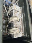
First look and see if the CT's are wired correctly. How many loops go through them? Should be 8 times for a MEP-802A.

The S6 has nothing to do with your problem. Its for meters only. S8, not you may just wind up taking it apart, of simply loosening it. up. Get more spray into the switch then.
 

Bassfishin114

Member
19
33
13
Location
Orlando Florida
First look and see if the CT's are wired correctly. How many loops go through them? Should be 8 times for a MEP-802A.

The S6 has nothing to do with your problem. Its for meters only. S8, not you may just wind up taking it apart, of simply loosening it. up. Get more spray into the switch then.
can you elaborate on”CT’s” I am not sure what that means.
 

Scoobyshep

Well-known member
1,134
1,508
113
Location
Florida
can you elaborate on”CT’s” I am not sure what that means.
Current transducer (or transformer) it's how the instrumentation measure current. The number of wraps changes the current multiple. Look for a block with wire wrapped through a hole

Sent from my SM-S908U using Tapatalk
 

Bassfishin114

Member
19
33
13
Location
Orlando Florida
Current transducer (or transformer) it's how the instrumentation measure current. The number of wraps changes the current multiple. Look for a block with wire wrapped through a hole

Sent from my SM-S908U using Tapatalk
There is 16 wires through each loop.

I found another post that mentioned measuring AC voltage across K8 and found that with a small space heater
K8-1 and K8-4 has 1v
K8-2 and K8-4 has 1v
K8-3 and K8-4 had 2v.
I am assuming that the last one having 2v is going to be what is causing the overload to trigger.
 

Attachments

Last edited:

kloppk

Well-known member
Steel Soldiers Supporter
2,145
3,526
113
Location
Pepperell, Massachusetts
It could be that resistor R13 is bad or the contacts 13 14 in S8 aren't making good contact. The purpose is to put R13 in parallel with R12. This cuts the burden resistance from 7.5 ohms to 3.75 ohms.
The CT's generate a current proportional to the load on the respective winding set. The CT's current flows thru the burden resistor and generates a voltage across the resistor. K8 measures that voltage across the burden resistor to determine if there is an overload.
If they aren't in parallel the voltage to K8-3 K8-4 will be twice what it should be. K8 uses that voltage to determine if there is an overload in that winding set. So... at 60% load K8 thinks that winding set is 120% loaded.
Screenshot_20230829_201311_Samsung Notes.jpg
 
Last edited:

Bassfishin114

Member
19
33
13
Location
Orlando Florida
It could be that resistor R13 is bad or the contacts 13 14 in S8 aren't making good contact. The purpose is to put R13 in parallel with R12. This cuts the burden resistance from 7.5 ohms to 3.75 ohms.
The CT's generate a current proportional to the load on the respective winding set. The CT's current flows thru the burden resistor and generates a voltage across the resistor. K8 measures that voltage across the burden resistor to determine if there is an overload.
If they aren't in parallel the voltage to K8-3 K8-4 will be twice what it should be. K8 uses that voltage to determine if there is an overload in that winding set. So... at 60% load K8 thinks that winding set is 120% loaded.
View attachment 904693
Well I started tracing wiring and looking at the R13 resistor and found one of the wires just sitting on lead. Soldered it back in place and it back to working properly. Thanks everyone for all of the help.
 
Top