• Steel Soldiers now has a few new forums, read more about it at: New Munitions Forums!

  • Microsoft MSN, Live, Hotmail, Outlook email users may not be receiving emails. We are working to resolve this issue. Please add support@steelsoldiers.com to your trusted contacts.

Missing circuit interrupter - MEP-831A

poultrydoc

New member
9
0
0
Location
Austin, TX
I bought this generator a couple months ago and finally got around to trying to fire it up. After attaching batteries, adding new oil and fuel, she fired up on the first try; however she wasn't putting out power.
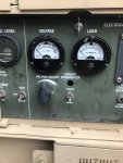
A closer look and the Circuit Interrupter light is missing (see pics) and the "overload short circuit" light is illuminated.
After reading through several posts on this unit and trying to troubleshoot the issue I started with trying to eliminate any moisture in the inverter. I let it run for 20 minutes, killed it then let it sit for a couple hours while I worked on something else, came back started it back up and it solved the problem - if everything worked out this well....

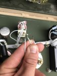
With that said, I'm still missing the light. Does anyone know if this is a standard part? Can someone take a pic of the back side of the control panel and give me a better idea of what I need and how to wire it.
Thanks in advance.
 

Guyfang

Moderator
Staff member
Moderator
16,697
23,926
113
Location
Burgkunstadt, Germany
Why don't you download the TM's for this gen set from the TM section? Then look up the part. Then use the NSN given in the TM, to get one?

When you get the part, the wire schematic in the TM will show you how to properly connect it.

The short circuit light could have come on because one of the wires that should be attached to the light socket was touching the frame/door.
 

poultrydoc

New member
9
0
0
Location
Austin, TX
Thanks for the helpful comment.

Let me try this again... I was trying to get out of the door yesterday and forgot to attach the photos.
I key word searched the TM I have (9-6115-639-13&P) for "circuit interrupter", but there are no hits that show a wiring diagram. I was hoping to tap some existing knowledge here before spending too much time on my own. Thanks in advance for the help.

[URL="https://photos.google.com/photo/AF1QipNeCbfvFOD4Pfg4-RgEx-OHO7XW7xnVCN6tpvsl"]


IMG_1218.jpgIMG_1219.jpg

[/URL]
 

DieselAddict

Well-known member
Steel Soldiers Supporter
2,531
2,058
113
Location
Efland, NC
What you are showing as missing there is the indicator light. It is DS6 on page 585 of the manual.
 

Guyfang

Moderator
Staff member
Moderator
16,697
23,926
113
Location
Burgkunstadt, Germany
You should find on the back of the control panel, and next to most components mounted anyplace on the set, a discription. Like DS6, or K1. It helps you find the items on the schematic much easyer. If you do not find the markings, then someone did sloppy work at reset. All sets came from the factory marked.

The light is easy. One wire is ground. One wire is 24volts, for the press to test function. The last wire goes to K1, (I think). In any case, the wires are numbered. Easy street. The 24 volt wire is probably the reason you got a short circuit light. It touched the control panel door.
 
Last edited:
Top
AdBlock Detected

We get it, advertisements are annoying!

Sure, ad-blocking software does a great job at blocking ads, but it also blocks useful features of our website like our supporting vendors. Their ads help keep Steel Soldiers going. Please consider disabling your ad blockers for the site. Thanks!

I've Disabled AdBlock
No Thanks