- 531
- 838
- 93
- Location
- Texas Hill Country
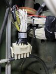
The 18550-99999 .PDF already here on SS? R13/P250 is in there, its on page 20…
View attachment 918554

R13?
Steel Soldiers now has a few new forums, read more about it at: New Munitions Forums!

The 18550-99999 .PDF already here on SS? R13/P250 is in there, its on page 20…
View attachment 918554

Yep, its not listed in the equipment reference lists in either of those documents, but R13 and its P250 connector is shown in the drawings in both those .PDFs on page 20… That is one thing I don’t like about these A1 drawings, the equipment ref doesn’t list the connector locations either like they did in the A0 drawings. Not very friendly when you are trying to identify things, like “what the heck is this grey thing”
Yes, not in the index, though on the J1939/1587 bus page in both. Once again I bow to you Ronmar.The 18550-99999 .PDF already here on SS? R13/P250 is in there, its on page 20…
View attachment 918554
No, i think that J version is good info to have available. There may be some other differences that we might not know about until we actually try to reference something specific.Yes, not in the index, though on the J1939/1587 bus page in both. Once again I bow to you Ronmar.
It shouldn't be added to the TM's, my mistake. Let us remove it—

J913 on page 10 B/C 3/4 area.Senior moment:
a year+ ago, before I had these new A1 schematics, I spliced into wires 1925 and 3020NN based on the TM diagrams which don't match this. I didn't use the splice so it's just taped off. I'm pretty sure this unused connector is the "options panel" connector which I don't have. 1925 powers up to 25v in ignition on. 3020 references TB2. Problem is, I can't find 1925 anywhere in the schematics nor can I find the J913 shown. So I'm not quite sure what I've tapped into, exactly. Trying to find a good 24v ignition source for my gps speedo.
View attachment 919250
Ok I'm seeing that. I remember now that I was trying to pull Power off the pto feed bc I don't have a pto. 1925 is shown in the TMs as PTO related, but not shown on the fmtvA1 diagrams. Seems like a workable concept since that J913 is unused. Lots of wires in that console. I can see now why the Canbus is so popular.J913 on page 10 B/C 3/4 area.
Wires 1904 page 4/58 connects to trans ecu PTO sensor, PTO on/off and CB49 off X3 at the PDP; and and 2019 goes through P913 to K37 (PTO) on page 4 C 2/3 area.
That may support the options panel idea—
1925 is on page 4/59 it is between CB49and the PTO on/off switch, 1904 is on the otherside of the switch—Ok I'm seeing that. I remember now that I was trying to pull Power off the pto feed bc I don't have a pto. 1925 is shown in the TMs as PTO related, but not shown on the fmtvA1 diagrams. Seems like a workable concept since that J913 is unused. Lots of wires in that console. I can see now why the Canbus is so popular.
AHHHH! how did you find that? That's great man! I've been scanning those pages for days looking for that friggin wire. So it IS the same as the TM at least for that circuit. That makes me feel good1925 is on page 4/59 it is between CB49and the PTO on/off switch, 1904 is on the otherside of the switch—
We get it, advertisements are annoying!
Sure, ad-blocking software does a great job at blocking ads, but it also blocks useful features of our website like our supporting vendors. Their ads help keep Steel Soldiers going. Please consider disabling your ad blockers for the site. Thanks!

