Afternoon. I am sorry if this has been posted, I could not find it. On the surface this question seems simple to me, but likely more complicated than expected. I picked up a MEP-804b genset with 46 hours on it a couple of months ago. Finally got the house and generator wired by an electrician that mostly does generators. He wanted to do a couple of checks before connecting to the house to avoid any possible damage. When I flip the switch to the closed position he gets the appropriate volts, amps, whatever in the wire, but the switch does not stay in the closed position. When I let go of the switch it returns to the mid position and no more electricity. Is this a 3 position switch that is supposed to stay in the closed position? If not, will the circuit remain closed if I have the generator connected to the house/load? Courtesy plugs work fine. It is wired single phase. Thank you for your insights.
-
Steel Soldiers now has a few new forums, read more about it at: New Munitions Forums!
no power 804b
- Thread starter Delmd92
- Start date

More options
Who Replied?- 16,667
- 23,828
- 113
- Location
- Burgkunstadt, Germany
Greetings!
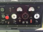
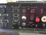
Yes, a 3 position switch. It should stay in the middle position, normally. To close the K1, output contactor, you press it up. The K1 should close, and stay closed, when you release the switch. Then you have to press the switch down, to open the K1 contacts.
As I understand it, when you try to close the S5, AC Circuit Interrupter, you have voltage on the output terminals. But lose it, when you let the switch go?
- 6,861
- 695
- 113
- Location
- Stratford/Connecticut
Its a momentary switch. Did it work before the electrician wired it? How did the electrician hook it up?
I did not have the means to test it before the electrician came. When I ran it to keep the batteries charged I was able to use the courtesy port and so didn't think the main power would be an issue.
Guyfang, you are correct. When I let go of the switch it returns to the middle position and main power is lost. So it sounds like the switch is working in that it is a momentary switch and is supposed to return to the middle, but will it only remain closed (main power fed to the line going to the house) if there is a draw/load on it? I could just hook it up and find out, but I guess I am following the electrician's lead and wanting to check this before blowing something up inside the house. I could reasonably live with blowing most anything in the house up, but the well pump is off the list of things to blow up. Thanks again.
Guyfang, you are correct. When I let go of the switch it returns to the middle position and main power is lost. So it sounds like the switch is working in that it is a momentary switch and is supposed to return to the middle, but will it only remain closed (main power fed to the line going to the house) if there is a draw/load on it? I could just hook it up and find out, but I guess I am following the electrician's lead and wanting to check this before blowing something up inside the house. I could reasonably live with blowing most anything in the house up, but the well pump is off the list of things to blow up. Thanks again.
- 6,861
- 695
- 113
- Location
- Stratford/Connecticut
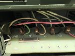
Connected load not required for the contactor to stay closed. The generator has some safeties that can prevent the contactor from staying closed. Over voltage under voltage. Frequency out of range. There are some trouble lights on the left and a test reset button. Once it's running you can put the battle short on and see if the contactor will stay closed. It is a 3 phase generator. Did the electrician just tap 2 of the 120 legs?
- 16,667
- 23,828
- 113
- Location
- Burgkunstadt, Germany
Sound advice. Try the S7 battle short trick and let us know how it went.
- 6,861
- 695
- 113
- Location
- Stratford/Connecticut
If everything appears to be working and the contactor won't close you can try disconnecting the wiring to the generator and see if that changes anything. Usually you will get an error light if the gen senses something that prevents output though. Download the troubleshooting manual and start working thru the issue.
- 16,667
- 23,828
- 113
- Location
- Burgkunstadt, Germany
Indeed, if you are not reading the troubleshooting diagram, you need to start.
According to the meters, you have power. So, try this. With the set off, place the S1, (start switch) in the run position. Place the S7, (battle short switch) switch in the up, (on) position. Then push up the S5 switch. The K1, (output contactor) should close. You will hear a "clunk". If no clunk, then you need to get into the -24 manual for the test procedure for the K1. Even if you hear a clunk, it doesn't mean the K1 is good. but lets just see if it will close, and STAY closed. Step by step.
According to the meters, you have power. So, try this. With the set off, place the S1, (start switch) in the run position. Place the S7, (battle short switch) switch in the up, (on) position. Then push up the S5 switch. The K1, (output contactor) should close. You will hear a "clunk". If no clunk, then you need to get into the -24 manual for the test procedure for the K1. Even if you hear a clunk, it doesn't mean the K1 is good. but lets just see if it will close, and STAY closed. Step by step.
Thanks for your patience. I assume the clunk would be obvious, no clunk that I can hear or feel over the pump.
I have downloaded every 804 and 803 manual that I have found on this forum. I have reviewed the trouble shooting sections. I do not see anything that I think resembles my situation in any of these manuals. I have done a search of this forum for "trouble shooting" and there are 8 pages, most not pertaining to generators. I have reviewed the relevant posts and have seen the reference to the -24 manual a couple of times. A search for this manual has come up equally vacant. Is there a specific, downloadable manual that I am missing? If so, my apologies for being unable to find it. Also, my apologies for seeming to be an arrogant newbie, but since this is such an important document and if it is available as a specific, downloadable manual, wouldn't it be advisable to make it a sticky somewhere easy to find? (At least easy enough for someone like me to find.) Under the 804 TM section, the only manual there is the engine manual, surely there are more manuals for the 804 that could congregate there. Sorry, rant done. I am happy to work through the steps necessary to solve this, if only I knew what I was supposed to be looking for and testing. If it turns out to be a bad switch, that is good news in some ways, not a simple Radio Shack switch, but easy enough to pull and replace. Thanks again.
I have downloaded every 804 and 803 manual that I have found on this forum. I have reviewed the trouble shooting sections. I do not see anything that I think resembles my situation in any of these manuals. I have done a search of this forum for "trouble shooting" and there are 8 pages, most not pertaining to generators. I have reviewed the relevant posts and have seen the reference to the -24 manual a couple of times. A search for this manual has come up equally vacant. Is there a specific, downloadable manual that I am missing? If so, my apologies for being unable to find it. Also, my apologies for seeming to be an arrogant newbie, but since this is such an important document and if it is available as a specific, downloadable manual, wouldn't it be advisable to make it a sticky somewhere easy to find? (At least easy enough for someone like me to find.) Under the 804 TM section, the only manual there is the engine manual, surely there are more manuals for the 804 that could congregate there. Sorry, rant done. I am happy to work through the steps necessary to solve this, if only I knew what I was supposed to be looking for and testing. If it turns out to be a bad switch, that is good news in some ways, not a simple Radio Shack switch, but easy enough to pull and replace. Thanks again.
robertsears1
Active member
- 255
- 119
- 43
- Location
- Near Apex/NC
Try liberatedmanuals.com and search mep-804b
Robert
Robert
- 1,176
- 388
- 83
- Location
- Guymon, OK
liberated manuals doesnt list the B on the -24, but the 9-6115-643-24 is what you need. The B is listed on the -10 above, and the -24P below.

http://www.liberatedmanuals.com/TM-9-6115-643-24.pdf

http://www.liberatedmanuals.com/TM-9-6115-643-24.pdf
- 16,667
- 23,828
- 113
- Location
- Burgkunstadt, Germany
OK partner, this is how it is set up. The below listed TM's are ALL the TMs needed to work on the MEP-804B. The reason there is only one manual listed under MEP-804B in the SS technical manual forum is this. The only difference between the MEP-804A and the MAP-804B, is the engine. So I assumed, and that gets me in trouble every time, I assumed that people who had a MEP-804B knew that. So, my bo bo. Sorry. All these manuals are in the SS manual forum. All the manuals for the MEP-804A are the manuals needed for the MEP-804B, except the engine manuals.
I am currently working up a list of ALL generator sets, and the manuals needed for them, set up so you can quickly see what you need for your generator, or Power plant/Power Unit, and the date of the latest manual, along with how many current changes are in that manual and whether you can HAVE that manual.
Some are Distribution coded A, Approved for public release; distribution is unlimited. And some are coded B or C or D. Those manuals are not to be released to the public, and we cant have them. All the MEP-804B manuals are coded A. Whenever I found a manual with a code of other then A, I tried to find an older TM, with a distribution code of A. Better and older manual, then none at all.
So Delmd92, these are the books you need. Had you looked better at the Engine TM 9-2815-538-24&P manual, under the chapter listed as: References, you would have also seen that the manual for the 804A model were supposed to be used for the 804B model.
Now, we can get down to bizness. I will post this, then I can go back to page one, and see what we were working on. Have patience, Delmd 92. I am an old man.
| MEP-804B | 15 KW | 4TNV84T-DFM | TM 9-2815-538-24&P | 15-Feb-09 | ||
| MEP-804B | 15 KW | LO 9-6115-643-12 | 31-Jul-08 | |||
| MEP-804B | 15 KW | TB 9-6115-643-13 | 1-Mar-02 | |||
| MEP-804B | 15 KW | TM 9-6115-643-10 | 15-Feb-10 | |||
| MEP-804B | 15 KW | TM 9-6115-643-24 | 1-May-08 | |||
| MEP-804B | 15 KW | TM 9-6115-643-24P | 30-Jul-10 |
- 16,667
- 23,828
- 113
- Location
- Burgkunstadt, Germany
Once again 155MM beats me to the punch!
- 1,176
- 388
- 83
- Location
- Guymon, OK
You just type slower than i do
- 16,667
- 23,828
- 113
- Location
- Burgkunstadt, Germany
I am old. What can I say.
OK, no clunk. Plan B.
A. Your gen set is making voltage. The meters read AC voltage. The freq meter reads Hertz. And your 120 volt outlets work. So the main gen is good. Be glad.
B. The part that allows voltage to go to your output cable, is K1, your output relay. K1 opens and closes when the S5, (AC Circuit Interrupter) switch opens and closes it.
C. The K1 relay is controlled by applying 24 volts to X and Y terminal.
D. K17 is the K1 Aux relay. It needs to work if the K1 is going to close.
So next step it to locate the K1 relay. So look in your TM's for the relay, and open up the set to find it. On the side of the relay, you will find some small wires connected to some screws. Find terminals X and Y. They should have wires 185L and 240A connected to them.
1. Start up the gen set.
2 connect a multimeter to K1, terminal X and ground.
3. Have your wife, or someone who is a trusted agent, flip S5 up, into the ON position, and see if you have 24 volts If you do, good. Let off S5. Did you lose voltage? If so, try looking at K17. See if it is working. It should move. Then test it IAW the TM. There is a procedure to check the relays in the book.
4. If you did not lose voltage, you need to then connect the multimeter to terminal Y, and to ground. If the relay is good, (and working) you would have voltage. In any case, pull out the K1, and test it IAW the TM. There is a test procedure for it in the manual.
Try getting this far, and let us know what happened.
Keep in mind. All the little plastic relays in the control panel are NOT the same. One is a switch, (but looks like a relay, and has a different part number from the relays) and the rest are all relays, with a different part number from the switch. If you do not have them in the right place, it won't work.
Thanks Guyfang, robertsears1 and 155mm. This is the type of info that I need. As I look at these TM's I have to give my respects to the engineers who designed these things, the people who assemble them and the mechanics who fix and maintain them. I guess I have a new course of study ahead of me. I was hoping to be able to plug and play this unit, but no such luck. I guess that is what frustrates me and unfortunately may come across in my posts. Thanks for your patience. I will come back and post a follow up when I have this done or more questions.
Guyfang, you are not alone in the "assume" situation. As is maybe clear in my earlier posts. I never really thought about similarities or differences between generators, just looked at the different numbers and figured they must not be the same. I am completely new to the military world. Willing to work on getting smarter, but right now it seems I have an expensive and heavy paper weight and just impatient to get it fixed and ready to go for the next power outage. Thanks again.
Guyfang, you are not alone in the "assume" situation. As is maybe clear in my earlier posts. I never really thought about similarities or differences between generators, just looked at the different numbers and figured they must not be the same. I am completely new to the military world. Willing to work on getting smarter, but right now it seems I have an expensive and heavy paper weight and just impatient to get it fixed and ready to go for the next power outage. Thanks again.
robertsears1
Active member
- 255
- 119
- 43
- Location
- Near Apex/NC
How did you arrive at getting an 804 to power your house? I bought mine to power three phase equipment. This size does not have a setting (like the 802 and 803) for 240 v single phase and the TM says that damage may occur to the generator pulling unbalanced single phase loads. A member here recently ran an 804 for several days to power his house during an outage (single phase) and did not incur any damage to my knowledge. I just know what I read in the TM but he had real life experience that seems contrary to the TM.
Robert
Robert
- 1,176
- 388
- 83
- Location
- Guymon, OK
If you are referring to me, yes i did power me casa on 2 legs of an 804a with no known damage. I even ran it again on my load tester, still pulls 18kw with no issues.
- 110,706members
- 165,193threads
- 2,324,410posts
- 1,303online users


