- 2,096
- 646
- 113
- Location
- Orlando, FL
A lot of people have problems with the CUCV charging system and I have been posting to individual threads in an effort to help people with alternator charging problems. Since I find myself posting the same thing over and over, I decided to put together a short thread on how to test the alternator on the vehicle. The test method I’m posting completely by-passes the vehicle wiring with the exception of the alternator B+ and B- leads. If you are unsure of their condition, wires can be connected directly to the battery the alternator normally charges. This removes any questions about the vehicle wiring causing problems since all the vehicle is doing is providing the mechanical power to drive the alternator.
I’m not going to get into the vehicle wiring because there are others that can trouble shoot the vehicle wiring better than I. I’m just going to help determine if the alternator works.
Test Setup:
1. The B+ and B- wires MUST be connected, either the vehicle wires, or wires you connect directly to the battery. Stock isolated ground alternators have a B- stud for the ground. The battery B- wire MUST connect to the B- post on an isolated ground alternator. If your drivers side alternator is not isolated ground, the mounting bolt is the ground.
2. Unplug the regulator plug. If you have a spare plug, you can use it for the test. Otherwise you can use a jumper clip. You can span both regulator terminals with the same clip because they both have to be connected to B+ for the test. Use two jumpers if necessary. Make sure you don’t short the jumper(s) to the case. If you use a test plug that connects to each regulator terminal separately, both wires have to connect to B+ for the test.
3. Connect jumpers from the alternator B+ and B- posts to the positive and negative leads of your DVM. You have to apply B+ to the regulator to turn it on once the engine is running so leave a place on the B+ lead to connect the regulator jumper(s) during the test.
Before you start the engine check a few voltages.
1. The DVM should read battery voltage from the B+ terminal.
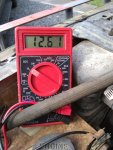
2. With the ignition switch on, regulator plug terminal #1 (closest to the B+ post) should read around 12 volts. Regulator plug terminal #2 will read battery voltage.
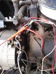
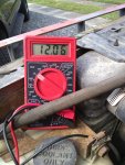
3. Start the engine. Once the engine is running, connect the regulator jumper(s) to B+. The regulator will turn on and the alternator should start charging. I’m using a test connector that is like the connector on the vehicle. That’s why there are two jumpers from the regulator plug and one from the alternator B+ post. BOTH REGULATOR TERMINALS HAVE TO BE CONNECTED TO B+ OR THE ALTERNATOR WILL NOT WORK!!!
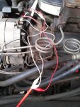
4. With the alternator working the voltage should be about 14.8. This is the regulator set point.
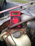
This should help determine if your alternator works. If the alternator does not charge, check your connections to make sure they are correct. Take the alternator and have it tested if you have any doubts. Make sure the person doing the test grounds the tester to the negative post if the alternator is isolated ground.
My alternator rebuild thread with pictues. https://www.steelsoldiers.com/threads/cucv-alternator-rebuild.146703/
Maybe a Moderator can make this a sticky for future reference.
I’m not going to get into the vehicle wiring because there are others that can trouble shoot the vehicle wiring better than I. I’m just going to help determine if the alternator works.
Test Setup:
1. The B+ and B- wires MUST be connected, either the vehicle wires, or wires you connect directly to the battery. Stock isolated ground alternators have a B- stud for the ground. The battery B- wire MUST connect to the B- post on an isolated ground alternator. If your drivers side alternator is not isolated ground, the mounting bolt is the ground.
2. Unplug the regulator plug. If you have a spare plug, you can use it for the test. Otherwise you can use a jumper clip. You can span both regulator terminals with the same clip because they both have to be connected to B+ for the test. Use two jumpers if necessary. Make sure you don’t short the jumper(s) to the case. If you use a test plug that connects to each regulator terminal separately, both wires have to connect to B+ for the test.
3. Connect jumpers from the alternator B+ and B- posts to the positive and negative leads of your DVM. You have to apply B+ to the regulator to turn it on once the engine is running so leave a place on the B+ lead to connect the regulator jumper(s) during the test.
Before you start the engine check a few voltages.
1. The DVM should read battery voltage from the B+ terminal.

2. With the ignition switch on, regulator plug terminal #1 (closest to the B+ post) should read around 12 volts. Regulator plug terminal #2 will read battery voltage.


3. Start the engine. Once the engine is running, connect the regulator jumper(s) to B+. The regulator will turn on and the alternator should start charging. I’m using a test connector that is like the connector on the vehicle. That’s why there are two jumpers from the regulator plug and one from the alternator B+ post. BOTH REGULATOR TERMINALS HAVE TO BE CONNECTED TO B+ OR THE ALTERNATOR WILL NOT WORK!!!

4. With the alternator working the voltage should be about 14.8. This is the regulator set point.

This should help determine if your alternator works. If the alternator does not charge, check your connections to make sure they are correct. Take the alternator and have it tested if you have any doubts. Make sure the person doing the test grounds the tester to the negative post if the alternator is isolated ground.
My alternator rebuild thread with pictues. https://www.steelsoldiers.com/threads/cucv-alternator-rebuild.146703/
Maybe a Moderator can make this a sticky for future reference.
Last edited:


