• Steel Soldiers now has a few new forums, read more about it at: New Munitions Forums!

  • Microsoft MSN, Live, Hotmail, Outlook email users may not be receiving emails. We are working to resolve this issue. Please add support@steelsoldiers.com to your trusted contacts.

CUCV alternator Problem

rockhopper1970

New member
6
0
0
Location
monticell/va
Hey Guys, I just got done rebuilding gen 2 on my truck. The bad news is that the gen 2 light is still lit. I've also noticed that when the engine is cold the voltage is in the middle of the green on the gauge, but as the truck warms up it starts moving too the yellow. does any one have any insight on this? Thanks in advance Rockhopper
 

Warthog

Moderator
Super Moderator
Steel Soldiers Supporter
13,774
232
63
Location
OKC, OK
Did you rebuild it or a shop?

Are all the wires hooked up in the correct place?

Have you tested the wiring?
 
Last edited:

Barrman

Well-known member
5,266
1,782
113
Location
Giddings, Texas
If your GEN 2 light is on, how are you getting voltage readings in the middle of the green on the gauge?

Put a volt meter on each alternator and see what it is actually putting out.

Also, once the glow plugs stop being used and the truck has been run long enough to top the batteries back up from what they used to start the engine. The alternators will pretty much stop charging since the only draw while driving down the road in the day light is the IP solenoid. That means GEN 2 is basically shut off and GEN 1 will just be giving a little trickle to refill the front battery. That will show up on the gauge with the needle moving closer and closer to the yellow as a long highway run is driven. Mine stops about a needle width above the yellow after about an hour on the road and stays there. I fire it back up and the needle is near the hash.
 

rockhopper1970

New member
6
0
0
Location
monticell/va
Warthog, I rebuilt it, wasn't too hard. I put the wires back on as they came off. also Barrman, I have no idea how the gauge is making it into green area with the light on but it is since i rebuilt it yesterday before the rebuild it always stayed in the middle of the yellow. Thanks for the insight into the charing system and how it drops after it rebuilds the starter/ glowplug amp drain back up.
Where should i start with the wiring, I already tried the delco manual test of removing the plug while running and the light went out when i did that.
 

Barrman

Well-known member
5,266
1,782
113
Location
Giddings, Texas
If the light went out with the plug on the side of the alternator pulled. That indicates a bad alternator. Have you put a voltmeter to the battery that alternator charges? With both leads on the post of that battery, you should have 12.6 engine off and 14.4 engine on.

I hate to say this, but you might need to pull the alternator apart again and test each part individually following the -34 manual or the Delco procedures.

See what voltage you get with the engine running first, then go from there.
 

rockhopper1970

New member
6
0
0
Location
monticell/va
Barrman,
thanks for the advice. I will try that tonight. just for background I did replace every piece on the back side of the generator (everything that was included with the kit) with the exception of the rear bearing, the capacitor, and the winding (the stationary copper wound piece?)

PAm1009,
I didn't think the rebuild was that difficult, but considering I'm still having an issue I can't say for certain.

Rockhopper
 

Warthog

Moderator
Super Moderator
Steel Soldiers Supporter
13,774
232
63
Location
OKC, OK
Sometimes new parts are bad. Double check the diode-trio.
 

M1008driver

New member
522
3
0
Location
Great Falls, Montana
This is probably not your problem, but clean everything connected to your 12 volt junction bar. The diamond shaped thing with the wires connected on the DS firewall under the hood. Of course you know that...
 

Warthog

Moderator
Super Moderator
Steel Soldiers Supporter
13,774
232
63
Location
OKC, OK
Check to make sure the fusible links for GEN2 are good. One on the 12v feed and one on the 24v output.
 

Warthog

Moderator
Super Moderator
Steel Soldiers Supporter
13,774
232
63
Location
OKC, OK
Not a problem.

http://www.steelsoldiers.com/cucv/74776-fusible-links-101-a.html

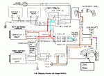
The GEN2 alternator is a 12v unit. Instead of a regular ground wire, it is fed 12v to the ground terminal and the unit will combine the voltages and output 24v (28.8v is a properly functioning system)

The 12v is fed to the alternator via a wire that is attached to the 12v terminal block by the brake master cylinder. This wire is protected by a fusible link. It is a blue wire attached to a red wire.

Also the GEN2 alternator is now outputing 24v and it is attached to the 24v Positive Terminal Block behind the rear battery.

It is also protected by a blue fusible link on the red wire.

I have attached a diagram of the GEN2 wiring.

Look at the colored wires - 8 RED 2C(SXL) and 8 RED/WHT 2A(SXL).
 

Attachments

Top
AdBlock Detected

We get it, advertisements are annoying!

Sure, ad-blocking software does a great job at blocking ads, but it also blocks useful features of our website like our supporting vendors. Their ads help keep Steel Soldiers going. Please consider disabling your ad blockers for the site. Thanks!

I've Disabled AdBlock
No Thanks