• Steel Soldiers now has a few new forums, read more about it at: New Munitions Forums!

  • Microsoft MSN, Live, Hotmail, Outlook email users may not be receiving emails. We are working to resolve this issue. Please add support@steelsoldiers.com to your trusted contacts.

12v alt wiring diagram

Seth_O

Member
625
7
18
Location
Sac CA
I spent some time on search this morning and found some threads where folks DID what I want to do, but no one specifically mentioned HOW.

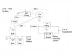
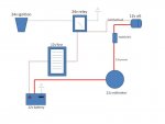
I am wiring up the 12v alt in my truck, and want to run it with a switched energized wire from a 24v relay, include a fuse box and a 12v voltmeter. I drew up the below rough diagram on how I think the wiring should be, but I am only good with simple wiring stuff.

Does this look right? The part I am the least clear about is wiring the full 12v power lead through the gauge, seems like it should run through a shunt or something? That's a lot of juice going through the dash. Anything else I am missing?
 

Attachments

steelandcanvas

Well-known member
6,187
85
48
Location
Southwestern Idaho
The only thing I saw was one side of the voltmeter needs to go to vehicle ground. It looks as though you have the voltmeter in series with the positive, which is OK for an ammeter, but not for a voltmeter.
 
Last edited:

Stalwart

Well-known member
1,739
33
48
Location
Redmond, WA
If you use a one wire alternator you only need the fusible link, and as Steel said above, the voltmeter connects to alternator output and ground. You can use your relay between the battery and the 12V loads to switch the supply but its not needed to "control" the alternator if you are using the one wire type.
 

Seth_O

Member
625
7
18
Location
Sac CA
If you use a one wire alternator you only need the fusible link...
I have the Delco 10si. I believe that's a 1-wire type, but it has a connection point for 'switched power'? That's how it's labeled on the alternator chassis.
 

steelandcanvas

Well-known member
6,187
85
48
Location
Southwestern Idaho
The part I am the least clear about is wiring the full 12v power lead through the gauge, seems like it should run through a shunt or something?
You would use a shunt in an ammeter circuit where the amperage exceeds the ammeter's measuring abilities. Here is a link I ran across while researching your Delco 10 SI. I gives some good information.
 
Last edited:

joshs1ofakindxj

Active member
735
118
43
Location
SW PA
Anyone want to check out my wiring diagram?

I'm using a 3 wire alternator. I'm not sure where to run the sensing wire. On the last offroad vehicle I had it on I just connected it to the ignition wire.

I have a 12v relay in place so that the 12v accessories turn off when I turn off the truck's ignition switch, but I also added a switch so that I can by pass that and have the 12v on when the truck is off, for example if I'm tailgating and want to listen to the radio.
 

Attachments

joshs1ofakindxj

Active member
735
118
43
Location
SW PA
Well everything works so far!

I got the relays working, tomorrow I will run power to the accessories and put in that relay over ride switch.
 

steelandcanvas

Well-known member
6,187
85
48
Location
Southwestern Idaho
Your schematic looks good, but I guess you already know that. You did the "smoke test" and the smoke stayed in the wires, that's a plus right there. I'm still questioning the load sensing and the alternator dash idiot light. I'm going to dig around and see what the difference is in the circuit. We are both on a learning curve, my Friend. Here is another link I found, it explains the idiot light a little better. Your best bet is to use the voltmeter in your circuit to keep an eye on the performance of your new 12 volt system. I think the logical place to install the voltmeter in your circuit would be the 12 volt output side of your switching relay, and then of course to chassis ground.
 
Last edited:

joshs1ofakindxj

Active member
735
118
43
Location
SW PA
I seemed to be finding wiring instructions with a Delco 10SI referring to that wire as load sensing and as for the indicator light. Bizarre!

I "thought" I just connected the load sensing and the field energizing wires together at the alternator on the off-road buggy I had this alternator on last but I discovered last night I had it connected to nothing. No load sensing in place, if that is in fact what the wire is for. I never had any charging problems on that buggy.

Last night when I did that part of the wiring I connected the load sensing or indicator light wire to the field energizing wire on the alternator because...well...just because I didn't think it would do any harm that way.

It seems like whether load sensing or indicator light power supply, it doesn't matter as long as the wire is connected to something that is ok to see a 12V source feed if it is in fact an indicator light wire and not a voltage sensing wire.

Now that I think about it, I think I'm going to run that wire straight to the battery. Indicator light or voltage sensing, it can certainly do no harm there.

If it is a indicator light feed that sends out 12V when the alternator is not charging, it might be letting my alternator energize when not in use if it is connected to the field energizing wire like I have it now. Not sure...

I was checking everything last night with a hand held voltmeter. It sounds like a good idea to install one on the circuit. Do you mean install it after the 24V relay or the 12V relay? 12V relay is where I'm thinking.
 
Last edited:

steelandcanvas

Well-known member
6,187
85
48
Location
Southwestern Idaho
I was checking everything last night with a hand held voltmeter. It sounds like a good idea to install one on the circuit. Do you mean install it after the 24V relay or the 12V relay? 12V relay is where I'm thinking.
My thoughts were (after looking at the Deuce wiring schematic) to get as close as you could to your 12 volt source, and have it switched so the voltmeter won't be powered up all the time. I was calling your 24 volt relay the "switching relay" since it is just an extension of the 24 volt ignition switch. Nice job by the way, don't you just love when a plan comes together?
 
Last edited:

joshs1ofakindxj

Active member
735
118
43
Location
SW PA
Thanks, but don't egg me on, I'm trying to be modest and humble! I know I'll create an electrical fire or something next week when I'm on to the next project.

I will get that voltage meter installed there once I get it out of my cherokee where it isn't hooked to anything. I agree with you on where to put it in the wiring.
 

steelandcanvas

Well-known member
6,187
85
48
Location
Southwestern Idaho
Thanks, but don't egg me on, I'm trying to be modest and humble! I know I'll create an electrical fire or something next week when I'm on to the next project.
I will get that voltage meter installed there once I get it out of my cherokee where it isn't hooked to anything. I agree with you on where to put it in the wiring.
No worries, you're a pretty good Apprentice Josh!
 
Top
AdBlock Detected

We get it, advertisements are annoying!

Sure, ad-blocking software does a great job at blocking ads, but it also blocks useful features of our website like our supporting vendors. Their ads help keep Steel Soldiers going. Please consider disabling your ad blockers for the site. Thanks!

I've Disabled AdBlock
No Thanks