• Steel Soldiers now has a few new forums, read more about it at: New Munitions Forums!

  • Microsoft MSN, Live, Hotmail, Outlook email users may not be receiving emails. We are working to resolve this issue. Please add support@steelsoldiers.com to your trusted contacts.

Picked up 6 MEP-802A gensets and will be documenting making them all runners here

rustystud

Well-known member
9,280
2,987
113
Location
Woodinville, Washington

pclausen

Well-known member
Steel Soldiers Supporter
452
281
63
Location
Afton, VA
Made some good progress today.

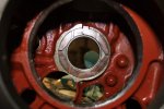
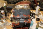
After a final touch up with the fine 400 grit hone stones, I pressure washed the block prior to final assembly.

MEP802-9-1-14-01.jpg
http://www.cstone.net/~dk/MEP802-9-1-14-01.JPG

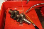
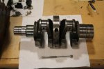
Next up was cleaning the crank.

MEP802-9-1-14-02.jpg
http://www.cstone.net/~dk/MEP802-9-1-14-02.JPG

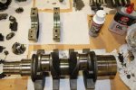
Center crank bearing ready to be installed. Got my green assembly lube smeared on the contact surfaces.

MEP802-9-1-14-03.jpg
http://www.cstone.net/~dk/MEP802-9-1-14-03.JPG

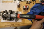
Torqued Allen bolts to 21 Nm

MEP802-9-1-14-04.jpg
http://www.cstone.net/~dk/MEP802-9-1-14-04.JPG

Greased up the backs of the thrust bearing halves and inserted into block.

MEP802-9-1-14-05.jpg
http://www.cstone.net/~dk/MEP802-9-1-14-05.JPG

Crank ready to be installed and I got my center bearing oil tube ready to go.

MEP802-9-1-14-06.jpg
http://www.cstone.net/~dk/MEP802-9-1-14-06.JPG

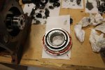
Next it was time to press the new seal into the rear bearing housing.

MEP802-9-1-14-07.jpg
http://www.cstone.net/~dk/MEP802-9-1-14-07.JPG

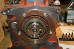
The gasket kit came with both a 0.015" and 0.020" shim for the bearing housing. I started with the smaller one and coated both sides with sealant as per the TM.

MEP802-9-1-14-08.jpg
http://www.cstone.net/~dk/MEP802-9-1-14-08.JPG

All done.

MEP802-9-1-14-09.jpg
http://www.cstone.net/~dk/MEP802-9-1-14-09.JPG

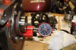
End play came in at 0.0125", so within the acceptable range of 0.0071" - 0.0149 per the TM.

MEP802-9-1-14-10.jpg
http://www.cstone.net/~dk/MEP802-9-1-14-10.JPG
 
Last edited:

pclausen

Well-known member
Steel Soldiers Supporter
452
281
63
Location
Afton, VA
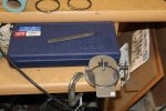
Next up was gapping the rings. Here's the neat little tool I picked up for the job. The regular wheel seems to do a great job. I did a final "deburr" using a fine file.

MEP802-9-1-14-11.jpg
http://www.cstone.net/~dk/MEP802-9-1-14-11.JPG

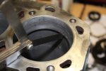
TM states ring gap should be between 0.01" and 0.02". I made all of them right at 0.01". Bores turned out to be very straight as I was getting the 0.01" gap all the way down to the bottom of both bores, so I didn't even bother with the digital bore gauge for this block.

MEP802-9-1-14-12.jpg
http://www.cstone.net/~dk/MEP802-9-1-14-12.JPG

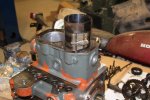
Piston #2 going in after a dip in Rotella 5W-40 synthetic (stuff I use in my Duramax). What is the recommended oil for these Lister engines?

MEP802-9-1-14-13.jpg
http://www.cstone.net/~dk/MEP802-9-1-14-13.JPG

Both pistons done.

MEP802-9-1-14-14.jpg
http://www.cstone.net/~dk/MEP802-9-1-14-14.JPG

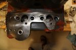
Machine shop still has the head for this engine. Hopefully they will get it done this week and I can complete the assembly shortly after that. Will get the oil pump, cam and governor done hopefully during this week as well.
 
Last edited:

pclausen

Well-known member
Steel Soldiers Supporter
452
281
63
Location
Afton, VA
Thanks Rusty!

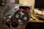
So got the gear back on the crank. Had to heat it quite a bit to get it hot enough (TM calls for "straw yellow" color, but I wasn't able to get it quite that hot). Anyway, it slipped on pretty easily with just a couple of light taps with a rubber mallet and a large socket.

Next I installed the cam.

MEP802-9-2-14-01.jpg
http://www.cstone.net/~dk/MEP802-9-2-14-01.JPG

Cam end play was 0.004" which is the lowest allowed per the TM (0.004" - 0.011"). I would think the less slop the better, so I'm happy with the 0.004"

MEP802-9-2-14-02.jpg
http://www.cstone.net/~dk/MEP802-9-2-14-02.JPG

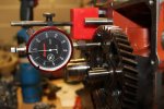
Now on the timing gear backlash, there was none. Standard Total Indicator Reading (TIR) should be 0.004" - 0.007" with a limit of 0.012" per the TM. I turned the crank 2 full rotation and it was smooth as butter with no binding anywhere. Maybe once I put a couple thousand hours on this thing, the gears will wear a little, and I'll have a little backslash. :)

Next I dropped in the lifers for the valves as well as the roller lifters for the injection pumps.

MEP802-9-2-14-03.jpg
http://www.cstone.net/~dk/MEP802-9-2-14-03.JPG

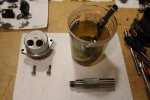
Lastly, I cleaned up the oil pump, pressure relief valve, and got the strainer soaking in Evaporust overnight as it had a bad case of surface rust.

MEP802-9-2-14-04.jpg
http://www.cstone.net/~dk/MEP802-9-2-14-04.JPG
 

Crabbie

New member
37
1
0
Location
Boise, ID
Peter, thanks for documenting your work so well. It helps us lurkers that are working on our own 802s in the shadows. I hope you don't have the same issues I am having, shot regulator and stator quad winding= no bueno on the voltage production. That is the bad news, the good news is that some of the 802s sold at the Crane auction are being parted out.
 

pclausen

Well-known member
Steel Soldiers Supporter
452
281
63
Location
Afton, VA
You're welcome Crabbie. My hope is that with 3 802s sitting around, I'll be able to swap electrical stuff around if needed, to get them fully operational, at least 2 of the 3. Funny you should mention 802s being parted out from the Crane auction. I picked up some 802 parts from one of those guys who had them listed on Ebay. Battery trays & hold downs and a few other misc part.
 

Crabbie

New member
37
1
0
Location
Boise, ID
Before you start the genset up be sure it has the fuse upgrade installed on the quad winding circuit as per TB 11-6115-741-24. Mine did not and I presume that is why it was sold. The 802a I am working on looks like the engine starter is new, so I presume there was an engine issue at one time that resulting in over cranking that wrecked the regulator and quad winding.
 

pclausen

Well-known member
Steel Soldiers Supporter
452
281
63
Location
Afton, VA
So even though that TB refers to the MEP804/805/806 gensets, it also applies to the 802?

I think my units already have those fuses, but I'll double check tonight.

Thanks!
 

pclausen

Well-known member
Steel Soldiers Supporter
452
281
63
Location
Afton, VA
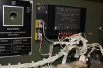
Sorry, I was looking at section 5.3 instead of 5.2. Fortunately, as it turns out, both the 2007 and 2009 units already had this mode done. Perhaps by 2007 they came like this from the factory? My 2006 unit does not have this mod, so I'll be sure to add it (assuming it otherwise test ok).

Here's the 2009. I plan to replace all those rusted screws...
MEP802-9-3-14-01.jpg
http://www.cstone.net/~dk/MEP802-9-3-14-01.JPG

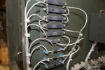
And while I was taking pictures inside the control box, I figured I'd take one of the "resistor bank" with a few diodes at the bottom.
MEP802-9-3-14-02.jpg
http://www.cstone.net/~dk/MEP802-9-3-14-02.JPG

On the engine, turns out I messed up by installing the cam before the oil pump. Guess that's what happens when several weeks pass between talking things apart and putting them back together... So I had to pull the lifters and then pull out the cam enough to slip in the oil pump. Worked out ok as I noticed the lifters were dropping some dirty oil. So apart they went.
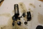
MEP802-9-3-14-03.jpg
http://www.cstone.net/~dk/MEP802-9-3-14-03.JPG

Cleaned up.
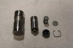
MEP802-9-3-14-04.jpg
http://www.cstone.net/~dk/MEP802-9-3-14-04.JPG

To reassemble, I sloshed some engine oil in the outer barrel, drained, then coated the inner barrel in oil and inserted in outer barrel with the spring attached. I then filled the inner barrel with oil, added the "dime" and the the top cap. Used a 1/4" extension (has smooth corners) and pressed down on the cap to insert the retainer clip. I got really good by the 4th one. :D

With that out of the way, I installed the oil strainer and oil pressure relief. The oil pressure relief was a pain to get threaded just right.
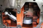
MEP802-9-3-14-05.jpg
http://www.cstone.net/~dk/MEP802-9-3-14-05.JPG

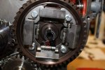
A shot from the front with all gears in place, and the crank and cam gears properly aligned.
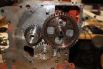
MEP802-9-3-14-06.jpg
http://www.cstone.net/~dk/MEP802-9-3-14-06.JPG

Tomorrow it's time to re-install the governor and time the injection pumps.
 
Last edited:

CDR

New member
325
3
0
Location
new york
Did you take apart the oil pressure relief??? This is a MUST!! it's easy to do and you don't have to remove the cam to do it
 

pclausen

Well-known member
Steel Soldiers Supporter
452
281
63
Location
Afton, VA
I thought about it but did not. But based on your suggestion, I'll be sure to do that as well!
 

pclausen

Well-known member
Steel Soldiers Supporter
452
281
63
Location
Afton, VA
Wow, yeah, yours looked pretty bad!

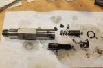
Here's mine once I took it apart.

MEP802-9-4-14-01.jpg
http://www.cstone.net/~dk/MEP802-9-4-14-01.JPG

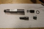
All cleaned up.

MEP802-9-4-14-02.jpg
http://www.cstone.net/~dk/MEP802-9-4-14-02.JPG

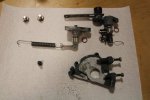
With that out of the way, I cleaned up the misc throttle levers and what not.

MEP802-9-4-14-03.jpg
http://www.cstone.net/~dk/MEP802-9-4-14-03.JPG

Installing those pieces was a real pain with the cam gear in the way. On the other engines, I'll definitely be putting those pieces in before the cam.

MEP802-9-4-14-04.jpg
http://www.cstone.net/~dk/MEP802-9-4-14-04.JPG

Talked to the machine shop, and they have not had a chance to look a the head next, but hopefully next week. I figured I'd be better off keeping the heads matched to the blocks they came from and not use the head they already did from the 2006 engine on this 2009 one.
 

CDR

New member
325
3
0
Location
new york
Your looks much nicer then mine! I feel bad that I didn't open the motor after seeing all the rust in yours. Mine seems to run good though
 

pclausen

Well-known member
Steel Soldiers Supporter
452
281
63
Location
Afton, VA
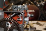
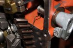
Got the governor weights back on the cam gear. One of the rollers was seized and left a flat spot (barely). It's the one with the red arrow pointing to it. I was able to break it free prior to installing, and it spins real smooth now after some lube.

MEP802-9-5-14-01.jpg
http://www.cstone.net/~dk/MEP802-9-5-14-01.JPG

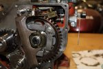
Governor itself installed.

MEP802-9-5-14-02.jpg
http://www.cstone.net/~dk/MEP802-9-5-14-02.JPG

Detail of the return spring for the throttle arm. I'm 99% sure this is how it goes. Can't really tell from the TM.

MEP802-9-5-14-03.jpg
http://www.cstone.net/~dk/MEP802-9-5-14-03.JPG

The throttle arm has like a primary "arm" (red arrow), and a secondary "arm" (blue arrow). The governor lever will catch on the secondary arm with the throttle throw all the way, and then ride it all the way back to idle position. I suppose there's a reason for this arrangement, but not really sure what. I might check the function on one of the other engines before putting the front cover back on to make sure the way I have it is how it's supposed to be.

MEP802-9-5-14-04.jpg
http://www.cstone.net/~dk/MEP802-9-5-14-04.JPG

Shot show the shims that go on each end of the governor pivot arm. Don't want to get those mixed up.

MEP802-9-5-14-05.jpg
http://www.cstone.net/~dk/MEP802-9-5-14-05.JPG

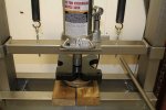
So the next step is to install and time the injection pumps. So far all I did was spray them down with brake cleaner and wipe off the caked on oil deposits. Should I take these further apart, drop them in Kerosene, or some other solution (like my carb cleaner solution), before installing them? I seem to recall that taking them apart was a bad idea?
MEP802-9-5-14-06.jpg
http://www.cstone.net/~dk/MEP802-9-5-14-06.JPG
 
Last edited:
Top
AdBlock Detected

We get it, advertisements are annoying!

Sure, ad-blocking software does a great job at blocking ads, but it also blocks useful features of our website like our supporting vendors. Their ads help keep Steel Soldiers going. Please consider disabling your ad blockers for the site. Thanks!

I've Disabled AdBlock
No Thanks