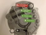
They are usually not difficult. Not sure what alternator that vehicle uses, but the typical connections are as follows, for most internally regulated alternators found on medium and heavy duty diesel engines:
B+= goes directly to battery +, may also be connected to starter B+ found close by, large wire
B- = goes to battery -, may also be connected to engine block or starter B- close by, large wire
There also could be a small wire which sends ignition voltage to the alternator to activate the field, or "turn it on"
There may or may not also be a second small wire, which is called battery sense, which detects system voltage at the battery bank, rather than at the alternator directly. Under full alternator output, the voltage difference between these two points can be as high as 0.9V or 1.0V.
Older alternators may also have connections for a warning lamp on the dash, and/or an AC output to send frequency data to a tachometer or engine hour meter (so the meter is not counting up when key left on).
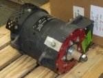
Some of the larger or dual voltage alternators used in military applications require an external voltage regulator box. Another thing to consider is the weight. A 200A alternator will likely be significantly larger and heavier than the 60A unit. May not hurt to compare the mounting bracket sturdiness of its original application vs the bracket on a 5T. You also have belt length, belt ribs, and vehicle wire harness considerations to make. The B+ wire designed to carry 60A is not going to like 200A, especially if any longer than a few seconds, if you are able to put 200A worth of load on it.
Included pic is photo ID of possible connections made to a current commercial over-the-road class 8 heavy duty truck. This alternator being completely self sufficient, and only needed the B+ cable connected to work (sometimes referred to as "single wire"), the remaining connections are optional, per customer.


