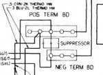
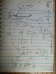
...I guess I'll need to replace the horn suppressor then, and any others that have failed. The PO also removed a bunch of suppressors, like the one for the windshield wipers, and I think he removed 1 of the 3 between the 24DC distribution blocks. Once I get the system working properly, I can add known-good suppressors back in...
I would recommend looking at non-GM specific potential solutions for RF suppression, once you broaded your view to things other than what the CUCV came with you will find many more options and sources. The most common method for reducing noise
across (radiated energy) a fast "switching" device is to use a capacitor, to kill the RF noise which is carried away (conducted energy) the most common way to kill that is a choke (coil of wire around a ferrite).
This article will echo what I just said, but you'll get a bit more depth than I have time for right now.
When taking care of RF radiating objects, a passthrough capacitor like the three GM put on the wiper motor and the one on the horn will reduce the effect of "sharp edges" in the current direction/flow - any time current changes rate or direction there is what equates to a "multi-car pile-up" of electrons, which sends out the "sound of the crash" as RF energy. If you can soften the change, it's like putting thick foam or pillows between each car, so the sound is much less (less radiated RF energy). The key is to get the capacitor as close as possible to the device generating the RF energy as any wire length between the capacitor and the device will act as an antenna (unintentional radiator). Quieting RF noise for FCC compliance was one of the things I did at my last job, it's both an art and a science (admittedly more science than art, the art comes into not affecting the performance of the thing we're quieting down, or its appearance).
If you are planning on putting on intentional radiators (antennas) for work related transceivers/receivers, I'd recommend doing some research on RF-bonding of vehicles. A diesel is less noisy than a spark ignited vehicle simply due to the lack of an ignition system, but some of the other issues (brushed motors, horns) are still there. If you put in modern LED fixtures or inverters, they often include high frequency switching power supplies which can radiate noise as well. The body can also act as many pieces of tuned RF metal which resonate at different frequencies - even your exhaust system can act like an antenna...
...It would be great if the current I'm detecting turned out to be a measurement error. I'm finding it very confusing. It varies from one day to the next. I was assuming that meant an intermittent problem, probably involving corrosion somewhere. Is there a reliable way to cross-check what the meter is telling me? I'm seeing current in the main battery cables. I don't see how measuring voltage would help me here. The Voltmeter does tell me what I expect to see, so the Fluke seems to be working OK... And I did zero the ammeter...
For very low current (<5amps) temporarily putting a current shunt in the circuit is safe - I mentioned via PM that I prefer to not use shunts in high current applications as they generate a good deal of heat as they approach their rating. If you don't want to go buy a retail shunt, just any resistor will do as long as it's power rating is sufficient: measure it's resistance outside of the circuit, then install it in series with the circuit being measured, then measure the voltage across it. Ohms law is what you use for figuring out how much current is flowing across the resistor:
Where E = Volts, I = Amps, R = Ohms. Divide the measured volts by the measured ohms and you'll get the current flowing across the resistor. If you have a choice in resistors, something that will amplify the measurement like a resistance of 10 Ohms or less (and multiples of ten makes the math easier). For instance a 10Ohm 50Watt resistor that shows 10milivolts across it works out to:
Code:
0.010Volts
---------- = 0.001 Amps or 1 milliamp
  10Ohms
This is safe because it's only using 0.01V * 0.001A = 0.00001 Watts or 10 microwatts (volts x Amps = Watts [power]). You can work out that this same 10Ohm 50Watt resistor will be safe for measurement up to 2.5Amps. Being in the millivolt range your Fluke 375 has an accuracy of +/-250microvolts or 0.00025V, so for measuring 1 milliamp your error would be +/-2.5% (very tight). Keep in mind most indicator type LEDs draw about 10-20 milliamps, so we're not talking a lot of power.
If you need to measure more amps, use a smaller resistor (1Ohm [100Watt is good for 10Amps], 100milliohm, etc...) with a higher power rating.
...It turns out a PO did the GP Resistor bypass, presumably to avoid the cascading failure that can happen when one GP fails, and the resistor provides higher voltage to the others, causing more to fail, etc. Didn't you do a highly mathematical analysis of that failure?...
I did - and if you don't use self regulating glow plugs the resistor system is fine. If you do use self regulating plugs (which have a variable resistance), I prefer to still keep the 24V supply but use something like
24V-to-12V DC/DC regulators for each plug (yes, 8x 25A regulators - takes about as much space as the two resistors, a little more). This way a standard 24V NATO jump plug can still be used to jump the truck (as glow plugs are needed to preheat the engine most of the time), but the energy efficiency of the glow system jumps immensely (from 50% to 90%+) and you can't have cascade failures since the voltage is limited.
...I do plan to keep the 24V starter, and various M1010 systems use 24V, like the A/C and fuel-fired heater. My winch is also 24V.
Try to keep as much of the original split system the same, it helps with troubleshooting later even if you swap say a ballast resistor pack for glow plugs with voltage regulators the function and design of the system stays intact for easy help later. Big devices with big power draw do better at higher voltages, that also means your cable size for the specific power demand will be about half the size (roughly one AWG step higher).


