• Steel Soldiers now has a few new forums, read more about it at: New Munitions Forums!

  • Microsoft MSN, Live, Hotmail, Outlook email users may not be receiving emails. We are working to resolve this issue. Please add support@steelsoldiers.com to your trusted contacts.

IL - M1009 Will Not Start

48cj2a

Active member
311
34
28
Location
Central, IL
Terminals removed and insulated and GP Card removed:

Key off - LtBlue card terminal contact: 0v
Key off - LtBlue card terminal contact: open circuit
Key on - LtBlue card terminal contact: 0v

Key off - Red control terminal: 0v
Key on - Red control terminal: 12v

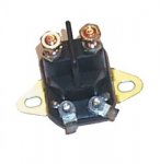
Installed the new S-603 Solenoid

Key off...
Red load: 12v
GP output: 0v
LtBlue: 0v
Red Control: 0v

Key on...No Clunk
Red load: 12v
GP output: 0v
LtBlue: 12v
Red Control: 12v

Key on...Grounded LtBlue: Solid Clunk (no buzzing)
Red load: 12v
GP output: 12v
LtBlue: grounded
Red Control: 12v


So before I wire in a momentary switch do I need to look at anything else?
 

tim292stro

Well-known member
2,118
41
48
Location
S.F. Bay Area/California
Sounds like your wiring is good [thumbzup], you can wire in a button or switch rated for the GP relay coil load - most use 10-20 Amp momentary toggle switches, but it's your call on what you want it to look like.

It's probably worth a quick shot plugging in the GP card to see if it is running right as-is. If you hook up the multimeter to the switched load side of the GP relay (orange wires) and the other lead to ground, and turn on the ignition with the GP card installed, you should see about 10-20 seconds of glow (12V) - again as has been said the wait light is not related to the glow relay, so you may or may not see glow when that light goes out. Keep an eye on the GP voltage when you plug in the GP card - if it has a failure that causes the GP relay trigger to short to ground, it'll make your glow plugs run until they burn out very shortly (between 1-5 minutes).

Keep it up, you're almost there! :beer:
 
Last edited:

48cj2a

Active member
311
34
28
Location
Central, IL
I did reinstall the card but did not check for voltage yet.

I double checked the fuses again and even ohm checked them to be sure. I did notice some wire taps in the fuse block and after yesterday's review of Warthogs fuse box information that I created a downloadable pdf, I need to see where this stuff is all going. There is an aftermarket radio installed, an odd looking dome lamp, a tap into the circuit 12 Voltmeter 24v source and there is also an on/off switch mounted next to the voltmeter but the owner does not know what it is for.


So I'm going to temporarily use my Sun Remote Starter Switch to ground the LtBlue terminal to at least attempt a start. I will do a test light test on all the GPs before I attempt this and also try an attempt at repairing the fuel leak in the filter base before a fresh fuel/air bleed/priming. It's been suggested that it may be the pressure switch but I have yet to pull the filter and look. Hopefully that is it and if I can get the correct o ring for the pressure switch otherwise I'll tap and install a screw to seal it.

Do you know if there are any other tests to eliminate the GP Card or any other areas to look at before going with the manual GP switch alternative. Would it be safe to try this card in another known good system? Marchplumber is near me and we could attempt a test on his M1009 if it would not damage his CUCV.
 
Last edited:

tim292stro

Well-known member
2,118
41
48
Location
S.F. Bay Area/California
One of the reasons I cautioned about watching the GP relay while you install the GP card, is that if the card has a bad output transistor that failed-to-short, the GP card will not require power to trigger the GP relay - it only needs to be plugged in if it has that failure mode.

If the glow plug card dose not have this failure mode, it's probably "safe" to install it into another known-good vehicle to verify operation. You will want to test the power at the GP card holder contacts, and then verify the sensor function.


  • Pink wire should have power when the ignition is on, nothing when the ignition is off - this is the same circuit as the Injection Pump's fuel solenoid
  • Orange wire should have power when the glow plug relay is on, nothing when the relay is off


Your questions about testing a glow plug controller card is inspiring me to build a test fixture for cards... basically what antennaclimber did to make his demo video is a test fixture. I'm also inspired to make a system/circuit tester fault-finder that you would plug into a GP card holder to verify the system it's plugged into is good...
 

48cj2a

Active member
311
34
28
Location
Central, IL
Update tonight before seeing your last post above.

Glow Plugs all test nice and bright with the test light ground on the the GP terminal and the touching battery + with the probe.

I hooked up my meter to the GP output orange terminal on the solenoid and grd...I also put my Sun Starter switch on the LtBlue Terminal of the solenoid and a engine block bolt. Got a mid 12v reading and slowly decreased to about 10v over about a 15-20 second engagement after a second cycle and while cranking.

This was all with the GP card inserted.

One strange reading is when I went to put the battery charger back on I opened the battery disconnect on the neg terminal of the front battery and the meter which was still on the Orange GP terminal very slowing climbed to 12v over a period of 15-20 seconds and held there. I reached down and grabbed the GP wire on cyl 1 and then the GP inself but did not notice any warming of the wire or the GP (not that it was lighting).

Could this be some sort of malfunction on the GP Controller Card letting the relay get a ground and powering the GPs that you were kind of alluding to?

Moving to fuel, I removed the filter and it look a little wet arount the pressure switch. I ended up destoying it on removal because I didn't see the little clip. I tapped the hole with a 10-32 tap and blew it out with brake clean. I then ran a stainless machine screw with tephlon tape into the hole. Douched it down with brake clean and retured the filter after it dried. I'll attempt to bleed the system again tomorrow once I have a second set of hands to crank for me.
 
Last edited:

cpf240

Active member
1,479
5
38
Location
Free in Northern Idaho
The battery disconnect is on the negative terminal of the front battery only? That would still leave the rear battery in the circuit, and I seem to recall reading posts here on SS where that can lead to bad things. Usually this comes up when someone is trying to stop a runaway starter, and they pull the negative cable. That is assuming, as I recall this one is, still in the 24v battery configuration.
 

tim292stro

Well-known member
2,118
41
48
Location
S.F. Bay Area/California
Quick sanity check is pulling the GP card.

Okay so you have a battery disconnect too. Do you have any 24Volt accessories/devices other than the GP relay and the starter motor? I have seen 12V taps get a back-fed through 24V devices like that when there is a battery disconnect opened.

Look at this diagram:
half-24V-backfeed.jpg
This shows two 12V batteries in series like in a CUCV, and two types of loads: 12 volt (blue line) which only connects to the bottom battery and ground, and 24V (green line) which only connects to the upper battery and ground. If you open a ground battery disconnect and three is a 24V load switched on, the 12V upper battery can actually back feed the 12V loads that are also on (red line in the center diagram) - because of the way transistors work they are polarity sensitive - think of it like a truck with no brakes, if you're driving up the hill under engine power you have control with the throttle pedal - once you get over the hill gravity is in charge... Transistors work somewhat similarly. They are "in control" one way and act like a piece of wire the other way.

The way you fix this is to put a Diode on the 12V battery feed (third diagram, rightmost). This prevents the power from travelling the wrong way on the +12 wire breaking open the possibility of a reverse flow.

So yeah, it's possible that you saw 12V on the GP relay control wires if it backfed the trigger transistor in the GP card and passed through the GP relay coil - if it's enough to energize the relay to conduct, you would have whatever power to the glow plugs that the back-fed 12V loads would allow.

Try disconnecting the +24V battery wire as well when you have the charger hooked up and see if all voltage stops on the GP wires.

By the way, if you do have 24V stuff turned on when you disconnect the ground and sensitive 12V stuff in your system, it's possible you can do some damage to it. I wonder if that's why so many people have trouble with glow plug cards on these trucks... I don't recall the factory ever having a diode to block reverse flow through 12V loads, but all the manuals always state "disconnect the battery ground first".

We may be onto something :beer:
 
Last edited:

48cj2a

Active member
311
34
28
Location
Central, IL
Yes, still 24v starter which he just replaced again recently because the first was replaced for some reason and the shop installed a 12v starter then smoked it.

I just eliminated the resistor so now the 12v on the GP solenoid is hot all the time from the firewall terminal.

His idea behind the disconnect was to stop a parasitic drain but this may be where it is.
 
Last edited:

Warthog

Moderator
Super Moderator
Steel Soldiers Supporter
13,774
232
63
Location
OKC, OK
The single disconnect work great in 24v system but in the CUCV 12/24v system you do need to disconnect both batteries.
 

48cj2a

Active member
311
34
28
Location
Central, IL
As I stated this morning in post #43 above - Last night I was double checking fuses and found some taps in the fuse block with one going into circuit 12 - the 24V/mtr tap. I pulled it last night. There is also a switch next to the 24v meter and a dash stereo so its probably one too. I double check these in the morning.


I pulled the dash bezel a little while ago to see where the switch was terminated and it appears to be wired to the dome lamp. I'll change that and tap into the under dash lamp circuit like it should be on the headlamp switch. This will make a good spot for the GP switch.

I'll advise him into a seccond disconnect or discuss going entirely 12v since I myself have another new 12v starter I could swap in and just sell his since its brand new.
 

48cj2a

Active member
311
34
28
Location
Central, IL
Winter storm running through here since Midnight last night. Looks like we probably got 4-6" of the first snow this season for Central Illinois, so its putting a huge damper on my troubleshooting today. Its also about 31 degrees and it was like 70 last weekend...

cucv snow.jpg

Since I want to at least get something constructive done, I ran to Oreilly's this morning and got a Prime Line 7-01860-1 Solenoid ($12.99) for the Doghead Starter Relay Mod and a Dorman 86915 Push Button Momentary Starter Switch ($9.99). With my Military Discount and a $5 off coupon...$16.92 - Not Bad!

7-01860-1.jpg86915-007.jpg

Drilled a 5/8" hole between the Blackout and Service Light Switches and made a custom "Glow Plug Label" with my Brother Label Maker and some 1" labels. I downloaded the ISO GP Symbol and printed it on my barcode printer before I left work last night.

gppushbutton.jpgdashlabel.jpg


If anyone wants one pm me for my address and send me a SASE and I'll mail you the custom push label and the ISO GP Symbol labels.

cucvlabels.jpg

I have a chopped up interior harness from my personal M1009 that I replaced with a Civilian Harness to gain the gauge cluster from my engine donor truck, so I made a GP Button harness from the 24V gauge wiring which has a nice two wire connector in it for future maintenace if needed already terminated with eye connectors that perfectly attached to the starter switch. Just need to crimp on a terminal to attach to the factory 6 lug ground buss in the dash and run the other end out to the GP Solenoid.

cucv switch.jpg


I had went ahead and pulled the Dash Bezel to see what the switch next to the 24v gauge was for and noticed some previous carnage on the wait/water in fuel lamp box and the area around the corner of the radio opening so allied some JB Weld to attempt a repair.

dashrepair.jpg

dashrepair2.jpg

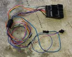
Joe - If you are serious about making the GP Card test fixture and do not already have something mocked up, I have the Glow Plug Card harness from my cut up harness that is completely in tact except either the Wait lamp or the Water in Fuel lamp lamp wires were cut, can't remember which.

gpharness.jpg
 
Last edited:

rsh4364

Active member
1,372
15
38
Location
greensprings ,ohio
As I stated this morning in post #43 above - Last night I was double checking fuses and found some taps in the fuse block with one going into circuit 12 - the 24V/mtr tap. I pulled it last night. There is also a switch next to the 24v meter and a dash stereo so its probably one too. I double check these in the morning.


I pulled the dash bezel a little while ago to see where the switch was terminated and it appears to be wired to the dome lamp. I'll change that and tap into the under dash lamp circuit like it should be on the headlamp switch. This will make a good spot for the GP switch.

I'll advise him into a seccond disconnect or discuss going entirely 12v since I myself have another new 12v starter I could swap in and just sell his since its brand new.
Its been getting pretty cold these past few years.I would advise on keeping it 24v,run your 12v supply from front batt.with a heavier gauge cable to a 140amp circuit breaker that way it still has a 12v shut off that wont effect rest of system.I think if you search cucv 140a circuit breaker you might find some more info.Its just a better way to do resistor bypass in my opinion.
 
Last edited:

48cj2a

Active member
311
34
28
Location
Central, IL
5f76f945bc99032e675921382b8b360a.jpg

Still pretty cold today, so only got the GP push button wires ran and terminated on the GP Solenoid.

gppushbuttonwires.jpg solenoidwire.jpg

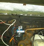
Dropped the starter relay bracket, mounted the new Doghead Relay and put it back together.

doghead.jpg

I'm hoping to bleed the fuel again early this week as its suppose to warm up to the mid 40s and start raining again.
 
Last edited:

Wagner

Member
Steel Soldiers Supporter
57
9
8
Location
Old Saybrook, Connecticut
My M1009 has developed a similar cold starting problem on the first start of the day. After the wait light goes off it has to crank numerous times before it will fire. While cranking you can observe smoke coming out of the exhaust and then when it does fire a huge exhaust cloud. Some times the GPR will continue to cycle after the engine is running....if shut the engine off and restart it a couple of time the GPR will usual quit cycling. After the engine has started once it usually will start fine the rest of the day with out excessive cranking.
 

48cj2a

Active member
311
34
28
Location
Central, IL
Check all your glow plugs. You could have a few dead ones. Maybe just 1.
Post #25 - They were all 2.8ohms during the #19 troubleshooting steps.

Post #45 - Glow Plugs all test nice and bright with the test light ground on the the GP terminal and the touching battery + with the probe.

Is there any other tests to confirm good or fried?
 

Wagner

Member
Steel Soldiers Supporter
57
9
8
Location
Old Saybrook, Connecticut
Thank you CUCVRS and 48cj2a for the helpful posts. I am currently about 1200 miles away from my M1009 and will not be able to perform the suggested GP tests until February though I will then. I also note with interest the discussion in this thread of various types of replacement GPs mentioned and I would be interested to know if anyone has discovered any new replacement GP options that improve fuel mileage and or performance.

Wagner
 

cucvrus

Well-known member
11,473
10,434
113
Location
Jonestown Pennsylvania
WOW. Glow plugs have nothing to do with fuel economy or power band increases. After the diesel engine has started from cold you could cut/remove the wires off the glow plugs and they are no longer needed until the next cold start up. They serve no other purpose other then ignite the fuel on cold start to start the internal combustion of the diesel engine. These CUCV's have a very crude old school diesel engine in them. 12 volts to the injection pump and you are off and running till you take that 12 volts away. Provided it has lubrication, Fuel and cooling.
 
Top
AdBlock Detected

We get it, advertisements are annoying!

Sure, ad-blocking software does a great job at blocking ads, but it also blocks useful features of our website like our supporting vendors. Their ads help keep Steel Soldiers going. Please consider disabling your ad blockers for the site. Thanks!

I've Disabled AdBlock
No Thanks