• Steel Soldiers now has a few new forums, read more about it at: New Munitions Forums!

  • Microsoft MSN, Live, Hotmail, Outlook email users may not be receiving emails. We are working to resolve this issue. Please add support@steelsoldiers.com to your trusted contacts.

Rebuilding the Injection pump

Beyond Biodiesel

Active member
373
37
28
Location
Prescott, AZ
The gasket kit is still available from "Ambac". Call Melody Feaster at 1-800-628-6894 . Tell her you need the gasket kit for the "PSB-6A" Bosch injection pump.
I browsed Ambac's website for the seal kit. I found this link on their web site. Is this the gasket kit for the "PSB-6A" Bosch injection pump? And, presumably, the "PSB-6A" Bosch injection pump is the pump that you are discussing here rebuilding for the Deuce?
 

rustystud

Well-known member
9,280
2,987
113
Location
Woodinville, Washington
No. That was the old major rebuild kit which is no longer available. You must buy the parts individually, but the gaskets still come in a kit. Again call "Melody Feaster" at 1-800-628-6894 . She has all the new part numbers and really knows this pump well.
 

rustystud

Well-known member
9,280
2,987
113
Location
Woodinville, Washington
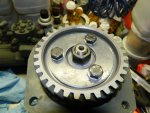
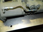
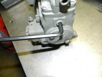
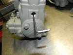
001.jpg002.jpg004.jpg

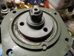
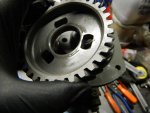
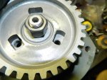
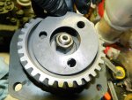
I forgot to add these pictures. Picture one shows the new "PTFE" stainless steel oil supply hose. Pictures two and three show adjusting the "droop" screw.
The "droop" screw is to help the governor with "surging" problems. In pump models that are installed in generators there is a special "droop" screw assembly that could be installed for quicker response times, but our trucks never needed them as our feet are better at that.
 

rustystud

Well-known member
9,280
2,987
113
Location
Woodinville, Washington
View attachment Scan0186.pdfView attachment Scan0188.pdfView attachment Scan0187.pdf

This is some more information about the different settings of the LDT and LDS pumps. Picture one shows how to adjust the main fuel on the "Fuel Density Compensator" . Picture two shows how much the LDT pump should put out at 2600 RPM's (37.5 to 38.5 cc/500 strokes) . Picture three shows how much the LDS pump should put out at 2600 RPM's (45.5 to 46.5 cc/500 strokes) . If my math is correct that is a 18% output increase for the LDS over the LDT pump.
 

rustystud

Well-known member
9,280
2,987
113
Location
Woodinville, Washington
This is a very interesting point. How does that work?
It basically helps keeps the governor from surging conditions, but in all honesty just using your foot to adjust the fuel if your slowing down is better in my opinion. That is why I believe the TM manuals don't go into such great detail about the droop screw. Now in generator applications that is very important as heavy loads coming on and off can cause severe power surges which can harm electronics.
 
Last edited:

stb64

Member
162
15
18
Location
hohenfels germany
It pushes back against the governor
I'm confused now. I thought the droop screw was part of the governor, and either it contacts the stop plate, and limits fuel flow, or, when it does not touch the stop plate, it does nothing.
What am I missing here?
 

rustystud

Well-known member
9,280
2,987
113
Location
Woodinville, Washington
I'm confused now. I thought the droop screw was part of the governor, and either it contacts the stop plate, and limits fuel flow, or, when it does not touch the stop plate, it does nothing.
What am I missing here?
What you need to do is look at the TM and you will see how the governor works. I can try and explain with words tell the cows come home and you will still not understand until you "see" it. TM 9-2910-226-35 is a good TM to use.
 

stb64

Member
162
15
18
Location
hohenfels germany
[What you need to do is look at the TM and you will see how the governor works. I can try and explain with words tell the cows come home and you will still not understand until you "see" it. TM 9-2910-226-35 is a good TM to use./QUOTE]

I've got a copy of TM9-2910-226-34, 1976 paper version.
When looking at the sectional view, it appears the droop screw only comes into play when it touches the stop plate.
By resting against the stop plate, the droop screw keeps the fulcrum lever from moving towards the ''increase fuel'' position.
How does this help add fuel? It seems to me, that it does exactly the opposite. What am I missing?
 

rustystud

Well-known member
9,280
2,987
113
Location
Woodinville, Washington
The droop screw keeps the governor from surging wildly by coming into contact with the "stop plate" before the "cam" . I think I know what the problem is here. Your not taking into account that the stop plate moves during operation. It is not stationary, but slides up and down according to fuel pressure. At 60 psi it is in its full open position and you can adjust the "guide adjusting screw" to increase max fuel as long as you keep an eye out on the Pyrometer.
As far as the TM goes, get the TM 9-2910-226-35 . It is a better manual.
 

rustystud

Well-known member
9,280
2,987
113
Location
Woodinville, Washington
View attachment Scan0189.pdf This might help you better understand the function of the "droop" screw. When the droop screw comes into contact with the stop plate first, it prevents excessive fuel delivery during acceleration and at medium speed under load allows the turbocharger time to spool-up preventing excessive smoke.
 

Floridianson

Well-known member
Steel Soldiers Supporter
7,409
2,503
113
Location
Interlachen Fl.
Greg thought the FDC stop plate only moved when the viscosity of the fuel changed. The orifice on the FDC is calibrated on the injection machine to only the emergency fuels listed. When the fuel changes then the FDC changes giving us the same throttle input for all the different fuels but same output. Think you said you bypassed your FDC but by removing the adjustment allen head it changed the orifice setting and the FDC might not read the emergency fuels correct butt its not a problem because we bypass. I think the FDC was a waist and as most of us know it must be bypassed to prevent engine oil contamination.
 
Last edited:

stb64

Member
162
15
18
Location
hohenfels germany
Now I' even more confused:

The droop screw, which can only rest against the stop plate, and keep the fulcrum lever from moving further towards the ''increase fuel'' position, does two things that are exactly the opposite?:
helps add fuel
prevents excessive fuel delivery

I think I know what the problem is here. Your not taking into account that the stop plate moves during operation
Greg thought the FDC stop plate only moved when the viscosity of the fuel changed.
(Floridianson)
Makes sense:

The pressure inside the FDC only changes when a different fuel is used.
The pressure inside the FDC is the same regardless of engine speed, and does not change during engine operation.

How can the stop plate move during operation? And how would movement of the stop plate cause surging?

This might help you better understand the function of the "droop" screw.
This already is my understanding of the droop screw's, and governor's, function. It is, basically, what i learned back when I was an apprentice at M.A.N.

As far as the TM goes, get the TM 9-2910-226-35 . It is a better manual.
Thanks. I'll see if I can access the manual at work.
 

Floridianson

Well-known member
Steel Soldiers Supporter
7,409
2,503
113
Location
Interlachen Fl.
Greg is correct in saying when at 1200rpm and correct pressure is established the FDC starts to compensate and moves to it correct position for the fuel being used. So it does move from when we start till 1200rpm then settles to the correct position. I have not tested the fuel pressure at 1200rpm so if Rusty says it's 60 psi then that is the pressure where the FDC is doing it's compensation for that fuel. I don't mess with FDC calibration as I will bypass them as soon as I get the truck.
 
Last edited:

rustystud

Well-known member
9,280
2,987
113
Location
Woodinville, Washington
Greg is correct in saying when at 1200rpm and correct pressure is established the FDC starts to compensate and moves to it correct position for the fuel being used. So it does move from when we start till 1200rpm then settles to the correct position. I have not tested the fuel pressure at 1200rpm so if Rusty says it's 60 psi then that is the pressure where the FDC is doing it's compensation for that fuel. I don't mess with FDC calibration as I will bypass them as soon as I get the truck.

I haven't bypassed mine yet. I probably will sometime in the future.
 
Last edited:

rustystud

Well-known member
9,280
2,987
113
Location
Woodinville, Washington
Now I' even more confused:

The droop screw, which can only rest against the stop plate, and keep the fulcrum lever from moving further towards the ''increase fuel'' position, does two things that are exactly the opposite?:


(Floridianson)
Makes sense:

The pressure inside the FDC only changes when a different fuel is used.
The pressure inside the FDC is the same regardless of engine speed, and does not change during engine operation.

How can the stop plate move during operation? And how would movement of the stop plate cause surging?


This already is my understanding of the droop screw's, and governor's, function. It is, basically, what i learned back when I was an apprentice at M.A.N.


Thanks. I'll see if I can access the manual at work.
The stop plate is continually being adjusted in small increments according to fuel pressure at that time. Since fuel pressure is adjusted according to engine RPM then that means the FDC is constantly adjusting and the amount of adjustment is dependent on the calibration of the FDC for which fuel type it is using.
 
Last edited:
Top
AdBlock Detected

We get it, advertisements are annoying!

Sure, ad-blocking software does a great job at blocking ads, but it also blocks useful features of our website like our supporting vendors. Their ads help keep Steel Soldiers going. Please consider disabling your ad blockers for the site. Thanks!

I've Disabled AdBlock
No Thanks