US6x4
Well-known member
- 1,274
- 2,359
- 113
- Location
- Wenatchee, WA
...heat your cab, that is. Your turbo will be hot enough already 
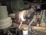
I wanted to chronicle my summer project and share my idea for an alternative heater mounting solution for M809s with a turbo installed (may work for other models also). This all started with the question of how to mount a heater if there is a turbo sitting in the heater's usual location so here is the idea in a nut shell:


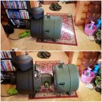
If you leave these two alone together in a dark room long enough - this is what will happen.
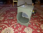
I first found an NOS M35 winterization kit for about half-off which was too good to pass up plus it had the diverter box with the inlet on the driver side which is where the heat would come from once a turbo displaces the stock heater location. I was staring at the drive side air cleaner one day thinking about relocating it to the passenger side of my M813 and having bolt holes and large air duct holes left in the side panel of the engine compartment and I thought I might as well leave one canister and just add the extra one. I could always store quarts of oil or something in one of them. Before my heater arrived I knew its length thanks to PartTarget and had the wild thought "maybe I can fit a heater inside of an air cleaner canister...hmm..." Luckily by brother bought me an extra canister for my birthday so I soon had all the parts to get started. From the first picture you can see that it will just fit, but to verify that it would work I needed to model up all the parts. Here is how it works:
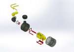
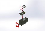
The yellow parts are what came with the winterization kit, the OD green parts are standard air cleaner pieces, and the red parts are the parts I had to design and manufacture to make this all work together. Modifying the heater box was simple, but modifying the air canister was tricky. For one, the 4" heater duct, the 14 Ga. power wire, and both 1 1/8" O.D. coolant hoses have to exit out of the 5" air cleaner outlet. All of this hinged on being able to re-route the coolant hoses into the heater box so that they could exit from inside the back of the heater box.


This funny looking part is responsible for that and a test fit shows that it will work! The oval part has the same perimeter dimension as a 4" thin wall tube even though it is squished down to make room for the heater hoses and power wire. Next I needed brackets to attach the heater box to the inside of the air canister.


This bracket is purely a bolt-on piece. It bolts to the heater box which in turn bolts to the angle irons you see underneath the bracket. These angle irons have tapped blocks welded to them and will be welded to the inner cylindrical wall of the air cleaner where the air filter once resided. Now it's time for some welding.


A lower gusset that you can barely see in the 3D model that goes between the inner and outer cylindrical shells and the weird hose outlet piece also got welded in, but I didn't get any pictures of them in the shop. Now it's time to modify the heater box which houses the heater core.


A new rear panel was designed with the outlet hole in just the right spot so that the canister outlet tube, which protrudes into the canister, would slip right into the hole while the heater box bracket rested on the angle irons previously welded in. This is where the 3D model was invaluable. The flat panel also had tapped block welded into the inside of the flanges and it was flat which made the overall length 1" less than with the original rear panel as seen in the middle photo above. This heater box still needs to reroute its coolant to the inside of the box...


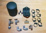
90 degree hose barbs, bulkhead fittings, and formed heater hoses allow the coolant to be directed into the heater box and out the back. I made a good guess on which formed shapes to use and it turned out perfect!
It looks like I ran out of allowable uploads so part 2 will continue with final assembly and mounting of all the pieces.
Stay tuned...
I wanted to chronicle my summer project and share my idea for an alternative heater mounting solution for M809s with a turbo installed (may work for other models also). This all started with the question of how to mount a heater if there is a turbo sitting in the heater's usual location so here is the idea in a nut shell:


If you leave these two alone together in a dark room long enough - this is what will happen.
I first found an NOS M35 winterization kit for about half-off which was too good to pass up plus it had the diverter box with the inlet on the driver side which is where the heat would come from once a turbo displaces the stock heater location. I was staring at the drive side air cleaner one day thinking about relocating it to the passenger side of my M813 and having bolt holes and large air duct holes left in the side panel of the engine compartment and I thought I might as well leave one canister and just add the extra one. I could always store quarts of oil or something in one of them. Before my heater arrived I knew its length thanks to PartTarget and had the wild thought "maybe I can fit a heater inside of an air cleaner canister...hmm..." Luckily by brother bought me an extra canister for my birthday so I soon had all the parts to get started. From the first picture you can see that it will just fit, but to verify that it would work I needed to model up all the parts. Here is how it works:


The yellow parts are what came with the winterization kit, the OD green parts are standard air cleaner pieces, and the red parts are the parts I had to design and manufacture to make this all work together. Modifying the heater box was simple, but modifying the air canister was tricky. For one, the 4" heater duct, the 14 Ga. power wire, and both 1 1/8" O.D. coolant hoses have to exit out of the 5" air cleaner outlet. All of this hinged on being able to re-route the coolant hoses into the heater box so that they could exit from inside the back of the heater box.


This funny looking part is responsible for that and a test fit shows that it will work! The oval part has the same perimeter dimension as a 4" thin wall tube even though it is squished down to make room for the heater hoses and power wire. Next I needed brackets to attach the heater box to the inside of the air canister.


This bracket is purely a bolt-on piece. It bolts to the heater box which in turn bolts to the angle irons you see underneath the bracket. These angle irons have tapped blocks welded to them and will be welded to the inner cylindrical wall of the air cleaner where the air filter once resided. Now it's time for some welding.


A lower gusset that you can barely see in the 3D model that goes between the inner and outer cylindrical shells and the weird hose outlet piece also got welded in, but I didn't get any pictures of them in the shop. Now it's time to modify the heater box which houses the heater core.


A new rear panel was designed with the outlet hole in just the right spot so that the canister outlet tube, which protrudes into the canister, would slip right into the hole while the heater box bracket rested on the angle irons previously welded in. This is where the 3D model was invaluable. The flat panel also had tapped block welded into the inside of the flanges and it was flat which made the overall length 1" less than with the original rear panel as seen in the middle photo above. This heater box still needs to reroute its coolant to the inside of the box...


90 degree hose barbs, bulkhead fittings, and formed heater hoses allow the coolant to be directed into the heater box and out the back. I made a good guess on which formed shapes to use and it turned out perfect!
It looks like I ran out of allowable uploads so part 2 will continue with final assembly and mounting of all the pieces.
Stay tuned...


