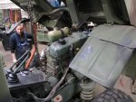
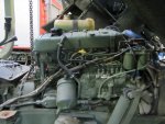
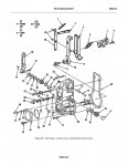
rtrask , I think the position of the top and bottom of the spring according to the adjustment of the rods is important.
Also think about clearance to the dog house and/or the cab.
View attachment 761285View attachment 761286
MigginsBros, Thank you.
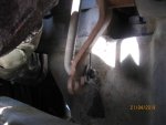
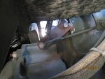
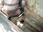
Your picture is worth 1000 words. It shows clearly what I had suspected. The lever for the throttle goes a lot further toward the back of the vehicle than mine does. I would bet a large sum that if you push the accelerator pedal all the way to the floor the spring never goes past or even close to vertical, which is the tipping point where the spring acts against it returning to idle. If you still have it tipped, you could help me a lot by measuring the approximate dimensions of the triangle formed by a vertical line passing through the place where the spring connects to the bracket, and the connecting rod and from that point to the swivel where the connecting rod attaches to the spring, and the stretched length of the spring. Labled side A, B, and C on the diagram below. Also while you are at it if you can give me the the length of the connecting rod from locknut to locknut that would be helpful too.

By the way that is the cleanest looking best maintained engine on a SEE I have ever seen. Kudos to you for your care of it.
Let me start out that the throttle liinkage on the SEE is nighmare worsened by how it it appears to added in once they fit the engine through the smallest hole in the cab they could. Add in the extra remote throttle for the backhoe and it get even more complex. That said I expect the Mercedes mentality meant that what thery designed works the way they designed it and if you dont like it dont buy it
.
About a year ago I started having issues with the linkage and made an adjustment to the long shaft on the injection pump side of the engine. Various folks with more skills suggested that I should determine why I needed to adjust something that was probably in the right place to begin with. I got it running and thought I was done with it. About a month later the whole linkage went to heck and i was stuck in the woods with a non functioning throttle. Turned out I had some bent components including the accelerator pedal and some parts on the inside of the tunnel that were bent out of shape probably from abuse and lack of adjustment over the years. I put some new those parts in and got everything working much better but its still not 100% occasionally refusing to turn off or on rare occasions pinning the throttle. I expect that if I undid my original throttle adjustment and spent a couple of hours I could get it back to the way it was intended. It is complex system but there are no shortcuts. I expect it would be much easier with the cab tilted and its on my list if and when I do finally have to tilt it.
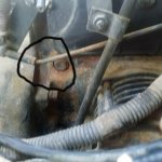
If you remember my linkage was badly bent too. I wondered at the time and still suspect that someone in the motor pool decided it was easier to adjust the throttle by bending the linkage rods than following the TM procedures. Since you have been through it without tipping the cab you know the incentive for taking a short cut (not excusing it, just recognizing the temptation). I agree in theory with what your “Various folks with more skills” said which is part of the reason for my post. But the “don’t fix it” wisdom is preceded by “if it ain’t broke,” So the problem is that it is broke. The question is how best to fix it and identifying what broke.
Since both you, pinsandpitons, and I suspect others have experienced similar problems it is not unique to me. The only variables are the rod connecting rod that I made, and the lever on the injection pump. Unless the connecting rod was replaced with the wrong one before I got it, the one I created was equivalent. Perhaps your wife is more understanding than mine, but putting a grand or more in to fix this problem by buying a new injection pump is not an option. Perhaps there is something serviceable on the injection pump I have that would allow me to rotate the lever. I am kind of afraid to go there. “If it ain’t broke, don’t fix it” keeps ringing in my ears, because the engine runs like a top right now.
When Mercedes designed it, they weren’t fools. Something has changed in the mean time for it to not work. On mine, the plastic hand throttle gets lifted to the side and swung down past the stop to kill the engine. When it is against the stop, it should be at idle. Am I miss-reading your statement that you move it against the stopto kill it?
Speedwoble There is no one that I respect more on this forum than you. You always give good advice. I know that the engineers that designed the system were not fools. So when I say that I think the design has a flaw, I mean no disrespect. There are always a lot of competing pressures that go into design decisions. I know that the vast majority of the 419s out there do not have this problem. All I can say is that the rod I replaced it with is the same length, and I need to find a solution. Currently my hand throttle kills the engine in exactly the same way as yours. You have to pull it out to get past the stop and give it a nudge to shut it off. From my reading of the TM 5-2420-224-20-2 pages 4-68 - 4-69 the correct adjustment is when the handle hits the stop. It should kill the engine. The decal on the dog house says the same thing. Also I don’t think the engineers at Mercedes would have you pull the hand throttle out and past the stop like that.
1. With engine idling, push hand throttle (1) all the way forward to its stop.
2. If engine continues to run, adjust accelerator linkage using following procedure:
a. Loosen nut (2).
b. Remove clip (3).
c. Disconnect ball socket (4) from pivot ball (5).
d. Turn ball socket (4) counterclockwise to shorten connecting link (6).
e. Connect ball socket (4) to pivot ball (5)TM 5-2420-224-20-2ACCELERATOR LINKAGE ADJUSTMENT (CONT)
f.Install clip (3).
g. Tighten nut (2).h.
Repeat step 1. If engine continues to run, repeat step 2 until engine stops running when hand throttle (1) reaches its stop.
3.If engine stops running before hand throttle (1) reaches its stop, adjust accelerator linkage using following procedure:
a. Loosen nut (2).
b. Remove clip (3).
c. Disconnect ball socket (4) from pivot ball (5).
d. Turn ball socket (4) clockwise to lengthen connecting link (6)
.e. Connect ball socket (4) to pivot ball (5).
f. Install clip (3).
g. Tighten nut (2).
h. Repeat step 1. If engine stops running before hand throttle (1) reaches its stop, repeat step 3 until engine stops running when hand throttle (1) reaches its stop.
NOTE: Follow-on Maintenance:Install inside engine hood (page 4-389).


