CUCV18series
New member
- 18
- 0
- 1
- Location
- North Carolina
M1008 turbo and serpentine swap
Hello Fellow Steel soldiers. I'm a long time follower of this awesome site. Have owned an M1008 and M1028 some years back, but had to sell them as they were my DD, and required too much work at the time to use reliably. About 6 months ago I got my hands on an M1008, intending to use it as a general farm truck for my homestead, as opposed to spending 70k on a new emissions and computer equipped diesel. The new to me M1008 has low mileage, a rebuilt engine, And also unfortunately came with a butchered 12v conversion.
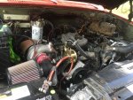
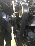
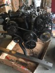
In this thread I'm going to detail a serpentine belt and turbo retrofit on my J code 6.2, using an F code civilian model 6.5 diesel donor engine. If you're an MV purist like I was with my first two CUCv's this probably isn't a thread you're going to like, as I "Mad Maxed" my current M1008 during this build.
1.) Starting out:
I started out by cleaning up the 12volt conversion following the Roscommon instructions, I installed the doghead relay mod, gear reduction starter (with shim and replacing the missing starter bracket mount) and a caterpillar spin on fuel filter mod. I debated returning to the 24V system, but I found I found it easier to fix the hackjob conversion.
2.) Selecting the right parts for the swap:
i debated between using a 6.5 turbo setup and a name brand commercial off the shelf turbo set up. I decided to use a 6.5 based off of the availability of oem parts, and the price point (most commercial kits I found were roughly $3,000)
I searched a salvage yard and discovered a high mileage 1994 Civy F code 6.5 motor. I chose the 1994 vintage due to the fact that it used the original GM serpentine setup (years included were 1988-1995) To my knowledge, GM switched the serpentine belt accessories around in the 1996 year, including a dual thermostat crossover. In my case, the trucks converted 12v system placed my alternator on the drivers side, which mirrored the GM 6.5 donor engine.
If youre going to do the serp swap, my recommendation is to find a complete f code 6.5 civilian motor (To my knowledge, the military 6.5's are incompatible) as there is very little OEM or aftermarket support for finding the parts you need. I had heard of folks several years ago, tracking down the parts on auction sites, but I found the market to be dried up when I was searching. I was able to purchase my donor engine for around $200. If you're just going to do the turbo swap, there are many 6.2/6.5 diesel performance sites where you can find all Thebes necessary parts.
3.) Tearing down the donor 6.5 for the necessary swap parts:
I set about tearing the 6.5 donor down, the following parts are what I needed for turbo swap:
-the intake manifold
-turbo
-turbo (passenger side) exhaust manifold
-turbo oil feed line
-turbo oil return line.
**the 6.5 came with a heat shield for the turbo exhaust manifold to protect the injectors and lines, but this will most likely not have the clearance to fit onto a 6.2 unless you also swap to 6.5 injectors.
**Additionally, the drivers side exhaust manifold from the 6.5 will hit your oil cooler lines and filter on the 6.2. I decided to retain my 6.2 exhaust manifold for the swap. I coated the exhaust manifold bolts in pb blaster at least three days before I started tearing into the donor.
4.) Parts needed for the serpentine belt swap:
-the alternator and power steering pump bracket (drivers side of block)
-secondary bracket that mounts from power steering pump to water pump stud and engine block
-coolant crossover and thermostat housing
- front engine hoist point bracket(very important piece, as this acts as a spacer to give you proper alignment of alternator and power steering pump pulley)
-A/C compressor bracket
-vacuum pump bracket
-water pump and water pump mounting plate/timing chain cover (necessary as this facilitates the use of a later model reverse rotation GM water pump for use in serpentine belt configuration)
-water pump pulley.
5.) Parts I ended up having to buy/replace:
-belt tensioner
-power steering pump/pulley
-CS130 alternator
-fluidampr harmonic balancer
-billet crank pulley
-A/C idler dummy pulley
-I chose to upgrade to a "desert grade cooling system" from a 6.2/6.5 performance retailer. This included a high output reverse flow water pump, Dmax fan, and severe duty fan clutch, 180 degree thermostat
I cleaned up and prepped any rusty brackets, and assembled new parts in accordance with a Haynes manual for 90's models trucks.
6.) Installing the serpentine belt parts onto the 6.2:
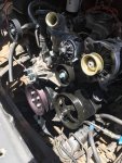
In order to swap the parts from the donor 6.5, I needed to first tear down the whole front end of 6.2. I also removed the radiator, radiator core support, and bumper so I had room to get around the engine bay. once I had torn it down, and covered any open lines (oil cooler, transmission cooler, power steering pump lines) I began installing the new parts from the donor 6.5, again following the Haynes manual for proper placement of sealant and torque specs. I installed the 6.5 donor parts in this order:
-harmonic balancer and new seal
-crankshaft pulley
-coolant crossover and thermostat housing
-Water pump/water pump backing plate/timing chain cover (I retained the 6.2 oil fill tube, in order to keep the CDR valve in semi original position, if you opt to not do this, you will need to swap your passenger side valve cover to the 6.5 version.)
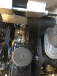
-front engine hoist point bracket and the alternator/power steering pump bracket. (The hoist bracket must be installed against the head before the accessory bracket, simply line up the holes and then bracket and bolts. This is what gives proper alignment for the power steering/alternator pulleys)
-A/C compressor bracket and A/C compressor dummy pulley.
*I waited till after completing the turbo install before installing the fan and fan clutch so that I could have free space in the engine bay.
** I chose to delete the belt driven vacuum pump that came with the 6.5 donor. The purpose of this vacuum pump is to run the waste gate actuator for the turbo. I opted to use a mechanical waste gate aka "turbo master". Since I chose to delete the vacuum pump the serpentine belt I needed had to be smaller than what a stock 6.5 runs. I opted for a 101" sized belt.
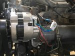
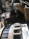
***One issue I ran into was alternator selection. I could fab up a bracket to retain the 27SI, but mine had gone bad (isolated ground post had literally corroded off) and in lieu of taking the chances with a rebuild I opted for a CS130 model that came stock with the 6.5 diesel. This meant I needed to purchase an adapter harness. This is a go between harness with pigtails to adapt a SI model alternator to a CS model. These can be found on various hotrodder retail sites for around $5. The model I selected was for a truck/car with an indicator light, as this is what is used to excite the alternator.
***The CS130 is grounded through its case, unlike the Isolated ground 27SI model from the original 24V set up. I am working off of a 12V set up. I do not have an answer for retaining 24V and attempting the serpentine swap with regards to alternator selection. I am sure someone here more experienced with the 24V system can weigh in better than me.***
7.) installing the turbo setup from the 6.5:
-I started out by removing the 6.2 air filter and air intake. I cleaned off the old gasket and installed the 6.5 turbo intake manifold with new gasket, and plenum and new gasket. I installed a vacuum line bolt into the center front bolt hole on the plenum, in order to install a boost gauge. I ran the excess vacuum line into the cab through the rubber grommet in the fire wall. I then reinstalled the ground wires on the rear most stud on the passenger side of the intake manifold.
-I then removed the mechanical fuel pump and pushrod from the engine block, and connected the input/output line and hose. I was able to find an aftermarket oil return line, complete with a fuel block off plate. If You have fabrication skills you could make your own and save yourself the $50 that it cost me.
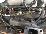
-Prior to installing the passenger side exhaust manifold, I cleaned the exterior off with a wire brush attachment on my angle grinder, and sprayed it with 3 coats of high temp ceramic primer and paint. I then used an air hose and ran it through the inside to break up any chunks/flakes of rusty iron. Once I completed cleaning up the manifold, I drilled and tapped a port for an egt probe. Just below where the turbo mounts to the manifold on the outboard side, there is a small flat extruded square shape. This is where I chose to drill and tap for the probe. Once the probe was installed I used heat wrap around the manifold to reduce under hood temps.
-The actual physical installation got a little tricky. I was unable to find replacements for the stock bolts and studs so I ended up buying:
(3) grade 8 70mm 10M x 1.5 bolts
(5) grade 8 90mm 10M x 1.5 bolts
*Studs were run in the stock configuration but I could not find any for this application and went with grade 8 bolts.
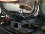
*Other guys who had done these swaps had recommended using two exhaust manifold gaskets to give yourself enough space between the block and manifold to avoid hitting the injectors and lines. Even with two gaskets, I still had rubbing on the center two injectors (my thought is that this was due to the exhaust wrap). I went to a local metal fabrication shop with an exhaust gasket manifold in hand and had them trace and waterjet a 1/4 mild steel spacer, and drill the bolt holes for me. This solved the lack of space between the injectors problem. This also made it impossible for me to fit the manifold, bolts, spacer and gaskets between the frame and the engine block, so I used a cherry picker and lifted the engine up enough to fit the manifold and bolt it in, as well as enough room to torque to spec. I made sure to pull the engine mount through bolts prior to raising the engine. For me, I only needed about 6 inches of space to be able to fit it up and attach. Using some strips of tape with dummy tabs over each individual bolt helped to hold them in place. I worked from the side closest to the cab and then forward. The three 70mm bolts are for the three bolt holes closest to the front end.
-I was then able to install the turbo, turbo oil return line, and turbo oil feed line. Prior to installing the feed line, I filled the port up with oil, and spun the turbine by hand to make sure I didn't dry start it.
-I didn't put faith in the original stock feed line holding up to the rigors of use, so I took it to a hardware store that makes hydraulic line and had them cut and crimp me a new line using the original fittings for about $10. While I was there, I bought the necessary pieces to plumb a tee into the oil pressure sensor port which already had an oil pressure gauge installed by the PO.
-I then fabbed up a 90 degree elbow and air filter coming off the turbo intake. I used a hole saw to create a hole large enough in the 90 degree elbow to accept a grommet, and installed a 6.5 CDR intake hose, which I connected to a CDR, and then ran a line to the original 6.2 CDR port on the engine oil fill neck. There's a lot of debate about people running CDR's vs a draft tube like a cummins does. I decided to stick with a CDR as that is how the engine was designed to run properly.
-Once that was completed, I simply connected the turbo and intake together with a silicone coupler.
I then installed my manual waste gate actuator aka "turbo master" in place of the original vacuum actuated waste gate controller.
8.) Finishing the build
-I then installed the water pump pulley and fan clutch/fan, radiator and lines and filled up with the necessary fluids.
-Once the front clip was back together, I climbed under the truck on the passenger side frame rail near the center crossmember. There is a rubber fuel line in this location. I removed the fuel line, and installed a 12psi diesel fuel pump commonly used in marine and reefer truck applications, mine came with a thread on proprietary fuel filter with clear housing. I grounded it at the frame and ran it to a relay and oil pressure sensor so that if the engine loses oil pressure, the pump will shut off (in the event of an accident, this is a safeguard to prevent continuous pumping of fuel that could ignite or spill all over the road).
9.) Post build problems to fix:
-I was then able to start the truck and bleed the air out of the fuel lines, power steering system and coolant system. The engine started and ran fine, had perfect oil pressure and sounded great (or at least sounded quieter, the fluidampr harmonic balancer and serpentine belt seemed to have taken out a lot of the rattling and vibrations, im sure the turbo intake manifold helped too.) I did have one issue however. The voltage meter was only showing at 12 volts. I used a multimeter to check the alternator current, and it read at about 12.08.
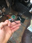
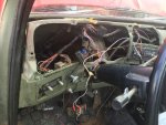
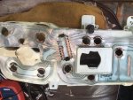
-The previously mentioned oil pressure gauge that had been installed by the PO was occupying the gauge port on the dash for the indicator/exciter light. Upon further inspection, I quickly realized that the PO had destroyed the printed circuit that connects the Gen exciter lights to install the aftermarket gauges. Additionally, the printed circuit itself was in pretty bad condition. To remedy the situation till I could find a replacement printed circuit and relocate the aftermarket gauge, I simply purchased a 12 volt indicator light, which I spliced into the brown exciter light wire coming off the alternator harness, and then ran a wire with a quick disconnect to the ignition powered ports on the under dash fuse block. Once the wiring was complete, I bumped the key and the indicator light lit up, and once I cranked the motor the light went out. I checked the current at the alternator and it was putting out a solid 13.8 volts, and the batteries were also charging in the same ball park.
-At this point I am waiting on a civy model printed circuit (the model that uses indicator lights in lieu of gauges), so I can get the dash cluster back to stock configuration. Once I rehab the dash, I plan on finishing my install of a four gauge pod (EGT, Boost, coolant temp, oil pressure) placed on the dash pad above where the voltage meter is.
-Once this is complete, I'm going to have the truck towed to a local exhaust shop for the crossover and exhaust pipe. I wish I could do this myself, but I lack a pipe bender in the garage. Once the pipes are installed, i should be able to dial in my boost in conjunction with my boost gauge. I plan on running the turbo boost at 8psi. The recommended max from other walkthroughs is approximately 10psi, so im going to stick with 8psi in the event of turbo surge or that my boost gauge is off.
Attachments
-
111.5 KB Views: 115
-
73.3 KB Views: 103
-
42.6 KB Views: 98
-
43.8 KB Views: 101
-
115.6 KB Views: 98
-
78.9 KB Views: 97
-
91 KB Views: 95
-
101.4 KB Views: 100
-
65.1 KB Views: 104
-
73.2 KB Views: 110
Last edited:


