• Steel Soldiers now has a few new forums, read more about it at: New Munitions Forums!

  • Microsoft MSN, Live, Hotmail, Outlook email users may not be receiving emails. We are working to resolve this issue. Please add support@steelsoldiers.com to your trusted contacts.

MEP 831A Fix-up Thread

CallMeColt

Well-known member
Supporting Vendor
1,026
1,475
113
Location
Wilson County, Texas
Alright, got the pull start & cup for it in. Installed & then made it so the pull handle is through the hole. Installed the new fitting that protects the rope. I rotated the pull start down a but so it has a straighter shot to the hole.

69649355_762492290874680_6314055031284826112_n.jpg70679350_436238310317994_1616930873410584576_n.jpg

Installed a 30amp twist lock outlet along with 2 110v outlet. Mounted it just below the convenience outlets.

69419304_901438696892041_1820561354587635712_n.jpg

Pull started it a few times. With it on casters now, makes it a challenge! I have had a few Yanmar engines like this so I know the pull starts aren't fun. I think the fact that the rope is at an angle & stuff doesn't help. Both times I pull started it, I had issues. First time, it did similar to what it would do when the controller or governor isn't set right will do & the engine went right down to a low idle when it was supposed to shut down. I cleared the low oil pressure. The second time, gauges showed 240v, cleared low oil light, but the contractor wouldn't close. It also again, wouldn't shut down. Is the pull start really only for is there is a dead or absent battery?

Also, no that I have more outlets, I tried loading it up a bit more. I maxed out the ammeter & it kept up pretty good. I noticed that the target lifted the linkage all the way out of the hole. Never got a overload trip or anything. Lots of smoke though. Maybe I just need to really burn it out at the 3000 watts first then go a bit higher to clean it out good?

Really thinking about getting kloppk's controller & selling my good one as a take off just to make it a bit more reliable. I'm not to confident will all the reports of bad controllers.
 

smokem joe

Active member
499
68
28
Location
Green OH
I just put one of Kurt's controllers in a one on Monday. Runs like a top now. Just sitting seems to make the stock one go haywire. I have a couple more to do now that I've seen firsthand how well they work getting rid of that factory controller.
 

kloppk

Well-known member
Steel Soldiers Supporter
2,145
3,526
113
Location
Pepperell, Massachusetts
...I noticed that the target lifted the linkage all the way out of the hole...
.
Hmmm... Something still isn't right with the adjustments. The rod should never be able to lift itself out of the hole.
The rod ball should always be in contact with the black lever when it's running or stopped. Never a gap between them when running or stopped.

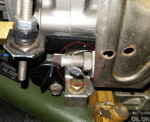
The ball lifting off the arm when running indicates the governor is trying to increase the engine speed but the black arm has hit it's stop and isn't allowing more fuel and any further increase in RPM.
There is another mechanical governor adjuster screw that you ought to check. It's located on the lower left of the mechanical governor. It too should be locked into place with a piece of wire and a lead seal. Since the rod is lifting out of the hole I suspect that adjustment screw in set way too far in and not allowing the engine RPM to increase up to the needed full load RPM. I believe that screw sets the maximum throttle point of the governor. The measurement for that screw on my two sets for comparison are:
0.890" & 0.900" from the top of the bolt to the plate it screws into.

Bottom Adjuster.png


When you ran your set at full load and the rod was lifting out your engine RPM was probably way too low for the load applied.
Did you check the AC voltage across A5 terminals 1 & 2 at full load? At full load the TM indicates you should see a voltage of 193+/-2 VAC or 288 Hz if your DMM can do frequency which corresponds to 3,450 RPM which is what the engine should be running at under full load.

I suspect the way your adjustments are set now the set is not running up to the needed 3,450 RPM under full load.
Do not run the set with a full load unless the engine RPM is close to the 3,450 RPM mark.
 

CallMeColt

Well-known member
Supporting Vendor
1,026
1,475
113
Location
Wilson County, Texas
When I made the adjustments last week, the reading was very close to what it should have been at a 3,000 watt load.

I don't think there's even a lower mechanical governor screw in my machine. After work today, I'm going to go look.

I figured the rod was lifting because it wanted to increase the RPM. The load was way higher than what the machine is rated for so I didn't leave it on long. How long does it take the overload circuit to cut the load?

I'm going to go through the controller setup again to see if it helps.

Thanks for the information!
 

CallMeColt

Well-known member
Supporting Vendor
1,026
1,475
113
Location
Wilson County, Texas
So, it is there & has the wire going through it, but it isn't to tight. I also don't see the little lead seal. The end of the screw has a small nipple that appears to be spring loaded. I will compare the measurements with what yours is & adjust a little bit to see if it helps.
 

CallMeColt

Well-known member
Supporting Vendor
1,026
1,475
113
Location
Wilson County, Texas
I spent a little time messing with it. The wire was actually cut but was put back in place to look like it wasn't at a quick glance.

I adjusted it out a little to let the engine rev higher. Seemed to help, but at the over rated load, the rod still lifts out of the hole.

I checked again, and at 3,000 watts, 240v load exactly, I am right at 193 volts / 288 hertz.

When taking this reading from the controller for the RPM, is this reading a true reading of the RPM or is it a reading of what RPM the controller is trying to create? If that makes sense.

Still going to go through the whole adjustment procedure again next week sometime as I will be away this weekend. Want to get it dialed in. Holding out for kloppk's combination WiFi & Governor Controller. Once that is ready, I will upgrade. Probably will do my MEP-802A as well.
 

CallMeColt

Well-known member
Supporting Vendor
1,026
1,475
113
Location
Wilson County, Texas
I just came inside from running through the controller setup again.

Put mechanical governor lower screw at 0.9in away from the plate it screws into.

Got my voltage readings right where they should be at all the stages. After going through the adjustments to the controller so many times, it goes rather quickly. :)

I noticed now that at full load, the rod is lifting out of the lever by about 1/4 in. I looked as best I could with a hot engine running & it seems that the lever isn't lifting up all the way to the little spring loaded nipple at the end of the lower governor screw.

Either way, I was getting proper reading between A & B on the controller.

Any thoughts or input anyone?

I'm thinking maybe to just let it run a bit under load as it may need some time to clean itself out? Possibly a bad/worn spring on all the governor parts?

Fuel generally can be an issue with diesel not coming up to proper RPM but the fuel all seems to be fine. Brand new filter. Tank was pretty clean.

Since it seems to be at the governor, I'm not sure it's a controller issue.

Will mess with it more & if anything improves, I will report back.
 

CallMeColt

Well-known member
Supporting Vendor
1,026
1,475
113
Location
Wilson County, Texas
Does anyone know what the voltage should read across the hour meter?

How about voltage across the Circuit Interrupter light?

The TM doesn't say what it should be. It just says looked for back connections & to replace. I want to be sure that the voltage is right before putting new bulbs & hour meter in. Wondering if that is why they fried.
 

DieselGenAC

New member
53
2
0
Location
NJ
I think the hour meter is the same as in the 501/531 2kw units. If so, look for something like 10 to 40 volts DC.EDIT: From the TM, work package 0039 HOURS METER: INSPECTION, TESTING, REMOVAL, INSTALLATION"TESTING1. Release instrument panel by turning fastener. Open instrument panel slowly.2. Set multimeter for DC volts and connect across terminals of HOURS meter.WARNINGHigh voltage is produced when this generator set is in operation. Use care when workingaround an open control panel with the generator set operating. Improper operation and/orfailure to follow this warning could result in personal injury or death by electrocution.3. Start generator set and operate at rated voltage.4. If 35-45 VDC is present, wait approximately six (6) minutes. HOURS meter should move 1/10 of an hour.5. If HOURS meter does not operate properly, meter is defective and must be replaced."
 
Last edited:

Guyfang

Moderator
Staff member
Moderator
16,766
24,080
113
Location
Burgkunstadt, Germany
overall length0 5/8 inches maximum
filament designationc-2f
light output rating0 17/50 spherical candlepower nominal single rating
average life rating in hours1000
filament heavy duty service ratingnot rated
emitted light characteristiccolorless
light center length0 3/8 inches nominal
voltage rating28 volts nominal
wattage rating1 3/25 watts
base stylemidget flanged
bulb stylet (tubular)
bulb designatort-1 3/4
bulb light transmission characteristictransparent
current rating for which designed0 1/25 amperes nominal
rated average lifehours
burning positionany acceptable

6240-00-080-2012
 

CallMeColt

Well-known member
Supporting Vendor
1,026
1,475
113
Location
Wilson County, Texas
I think the hour meter is the same as in the 501/531 2kw units. If so, look for something like 10 to 40 volts DC.EDIT: From the TM, work package 0039 HOURS METER: INSPECTION, TESTING, REMOVAL, INSTALLATION"TESTING1. Release instrument panel by turning fastener. Open instrument panel slowly.2. Set multimeter for DC volts and connect across terminals of HOURS meter.WARNINGHigh voltage is produced when this generator set is in operation. Use care when workingaround an open control panel with the generator set operating. Improper operation and/orfailure to follow this warning could result in personal injury or death by electrocution.3. Start generator set and operate at rated voltage.4. If 35-45 VDC is present, wait approximately six (6) minutes. HOURS meter should move 1/10 of an hour.5. If HOURS meter does not operate properly, meter is defective and must be replaced."
This is from the TM for the 531A/501A units? The TM for the MEP-831A is 0033. Has basically no information. Says basically that if it's broken, replace it.
 

kloppk

Well-known member
Steel Soldiers Supporter
2,145
3,526
113
Location
Pepperell, Massachusetts
Does anyone know what the voltage should read across the hour meter?
With the set running you should see ~ 28 volts DC across the Hour Meter terminals.


How about voltage across the Circuit Interrupter light?
Terminal 1 should have ~24-28 volts DC on it when S1 is in the RUN position.
Terminal 2 should have 0 volts DC on it with the contactor closed.
Terminal 2 should have ~28 volts DC on it with S1 in RUN and the contactor open.
Terminal 3 should have 0 volts DC on it all the time.
 

CallMeColt

Well-known member
Supporting Vendor
1,026
1,475
113
Location
Wilson County, Texas
With the set running you should see ~ 28 volts DC across the Hour Meter terminals.


Terminal 1 should have ~24-28 volts DC on it when S1 is in the RUN position.
Terminal 2 should have 0 volts DC on it with the contactor closed.
Terminal 2 should have ~28 volts DC on it with S1 in RUN and the contactor open.
Terminal 3 should have 0 volts DC on it all the time.
Thank you. I confirmed voltage was okay & installed new hour meter. Working!

What terminal is negative on the Circuit Interrupter light?

I'm asking all this because every TM file I can find, the DC circuit wire diagrams are very blurry. I tried to download a few with the same results. I took one of the indicator lights from my MEP-802A & it lit up for a quick second then died. Now it won't work & I'm trying to find a replacement for that as well. Found a few options but can't really confirm these bulbs are compatible to see if that is my problem or some sort of voltage issue.

There are so many options out there for these bulbs! I did find a good source with a large lot so maybe I'll just order a bunch & have extra.

I ordered two different complete assemblies & they arrived without bulbs. Go figure.

Thank you all again for the help.
 

kloppk

Well-known member
Steel Soldiers Supporter
2,145
3,526
113
Location
Pepperell, Massachusetts
The 802 one got "smoked" because you applied 24 volts directly across it's terminals. The 802 one needs a current limiting resistor with it. Without it you killed the 802 indicator LED.

PM me your email address and I'll send you a version of the TM that has very clear schematics in it.

You can check the wire numbers on the wires to the indicator to determine which terminal is which.
The wire numbers are in the pic below.
DS6.JPG

Replacement LED for the 802 interrupter.
https://www.oshkoshequipment.com/pr...ator-AC-Circuit-Interrupter-Panel-Light-Green

I could find suitable replacements from other places if needed.
 
Last edited:

CallMeColt

Well-known member
Supporting Vendor
1,026
1,475
113
Location
Wilson County, Texas
The 802 one got "smoked" because you applied 24 volts directly across it's terminals. The 802 one needs a current limiting resistor with it. Without it you killed the 802 indicator LED.

PM me your email address and I'll send you a version of the TM that has very clear schematics in it.

You can check the wire numbers on the wires to the indicator to determine which terminal is which.
The wire numbers are in the pic below.
View attachment 775802

Replacement LED for the 802 interrupter.
https://www.oshkoshequipment.com/pr...ator-AC-Circuit-Interrupter-Panel-Light-Green

I could find suitable replacements from other places if needed.
So, they are different. You'd think the military would make them the same.

Thank you for the picture & link. I did already find that website source yesterday.

Will send you a PM now. Could use the file with clearer pictures for sure.
 
Top