• Steel Soldiers now has a few new forums, read more about it at: New Munitions Forums!

  • Microsoft MSN, Live, Hotmail, Outlook email users may not be receiving emails. We are working to resolve this issue. Please add support@steelsoldiers.com to your trusted contacts.

MEP-005 Fuel Injection Pump

Guyfang

Moderator
Staff member
Moderator
16,779
24,115
113
Location
Burgkunstadt, Germany
Thanky Ray!

That should be the droop adjustment. The -34 TM has good info about the IP, and Droop adjustment, if I remember right. For some reason, lots of folks just HAVE to fool with the droop adjustment. Most never even read up what its supposed to do, just turn it. Give it a shot, and see if it works. While you are in the IP, pull the screen and make sure its clean. Look in the -34 TM, Figure 3-21, item 57. Normally, if this is dirty, EVERYTHING was dirty, at one time. Its an often forgotten filter, and when its plugged, its a head scratch er. No one remembers it.
 

Ray70

Well-known member
2,595
5,914
113
Location
West greenwich/RI
Well, here is where I'm at. I double checked everything under the top cover and reassembled. Took out the strainer on the fuel inlet and it was perfectly clean. checked the check valve on the fuel return also perfect. retested the fuel shut off solenoid and confirmed I can feel it hitting against the manual fuel shutoff lever when I apply power to it from the batteries. Also tried jumping the solenoid from battery and starting, still no fuel coming from the pump. I have good flow from the day tank to the pump. I also pulled the flat cover off the timing gear cover just to make sure everything looked ok.
The one odd thing I noticed that may be normal is that I initially removed the side window to drain the pump body. I left the fuel line attached and noticed it took almost 3 days before the pump body refilled ( 90%) by gravity. Also, it will not overflow if I left the top cover off indefinitely. Is that normal?
So now I'm wondering if there is anything else I can check with the pump on the motor? Or is it time to remove the pump and dig into it?
Note: to this point I have found no signs of dirt, gum etc. just the incorrectly tightened Droop knob ( which may have been my fault )
Thanks for any advise.
Ray.
 

Guyfang

Moderator
Staff member
Moderator
16,779
24,115
113
Location
Burgkunstadt, Germany
Ray,

If everything is hooked up again, and you take the small plate off the side of the IP, where you do the timing, turn on the electric fuel pumps. You should get a significant flow of fuel out of it.

If you disconnect the inlet fuel line, and direct it into a half liter container, the electric fuel pumps should fill it up in 30-40 seconds. Are you getting that much fuel?

Also, look in the -34 manual. PDF reader page # 105, Figure 3-21, sheet 3 of 7. You can, if you are VERY careful, pull the pump end apart. If the vanes are damaged, no fuel pressure. I went to the store, (because my wife would have killed me if I took one of hers) and bought a brand new, large white towel, to spread out below the IP. Should you drop something, it will make it MUCH easier to find, and the part will not fly off into the sunset. You can also, roll the engine over a bit by hand and see if the drive shaft is turning. But only turn it a bit. I had nightmares about turning the engine over with the starter, and the whole mess falling out. I don't know if it will, but sure hated to find out.

If you decide to pull the pump, and take it apart, read the -34 manual, several times about the IP, before you start, to get a feel for it. Your an old hand, so you know you have to time the engine/IP before removal. Procedure is in the -34, and its not hard. I will admit, I did not follow any of my above made hints and tips, the first time I pulled a pump. Took me several days to get the darn thing to run again. Repairing the IP was way above our level of work. I rarely did it, and wont claim more then 30-40% success. There was just too many extra tools and equipment needed to do it.

On replacing the IP, the double seal on the drive shaft needs a good coating of grease, and a steady hand, carefully sliding it back on. The first seal, rolls over, and your oil reservoir fills up with diesel in a blink of an eye. So take your time.

If you decide to take the pump to a shop, DO print out the test/repair portions of the -34 manual. Several folks in the forum had problems after IP "rebuild" work. Would not work right. Why? Because the standard adjustment to a civilian pump, are NOT the same as the Army pump. When they took in the procedures, then the IP's got adjusted right. One shop even left off a part, because they decided it wasn't needed.
 

Ray70

Well-known member
2,595
5,914
113
Location
West greenwich/RI
That's pretty much what I was thinking for next steps, check vane pump and verify shaft spins while I'm in there. I have a steady flow of fuel from the line, but from the window I doubt it, because it seemed to take almost 2 days for the pump body to refill after I drained it. However that was without fuel pumps running, but the system is gravity feed from the day tank ( which was full ) anyway.
This weekend I will check the vane pump, shaft and I'm also going to take a closer look at what the TM calls as a regulating spring ,piston and seal under the fuel inlet strainer.
Good idea with the towel.
If everything checks out then I will end up removing it to rebuild. I'll rebuild it myself, can't stand paying anyone to do something I can figure out on my own! Especially with a little guidance from those with experience, like yourself.:beer:
 

Ray70

Well-known member
2,595
5,914
113
Location
West greenwich/RI
Well Guyfang, Looks like I'll probably be rebuilding the pump at some point. I did more checking this weekend and still no smoking gun as to why I'm not getting fuel pressure.
I removed the rear cover and everything was good. Vanes all look good and the shaft turns fine. The fuel inlet is fine and it was perfectly clean, not a speck of dirt, varnish, nothing.
I took the timing window off again and with it reassembled and pump running I get a small stream of fuel out of the window. Just about enough fuel to create a steady trickle rather than individual drips. From the fuel line itself I get good fuel flow, a steady stream almost the diameter of a pencil that should easily give well over 1/2 liter / 30 sec.
At this point the only last thing I want to look into is exactly how the metering valve functions, just to be sure I didn't miss something when inspecting things under the top cover.
After that I think it's going to have to come apart.
 

Guyfang

Moderator
Staff member
Moderator
16,779
24,115
113
Location
Burgkunstadt, Germany
The absolute last thing I can think of is the someone else pulled your IP out, and put it back in 180 degrees out of time. Hook everything up, pull the last injector line off and turn it over. If you are getting good fuel, it's 180 out of time. My first IP job, I screwed up got the IP back in 180 out. Cranked it a day and a half. No start. Read the book, ( at last) and it said, big as day, if you put the pump in, and it won't start, turn the IP a compleat revolution, and put it back in.
Started right up, when I did that. Did the I
p look like it had been out before?
 

Ray70

Well-known member
2,595
5,914
113
Location
West greenwich/RI
Hi Guyfang. I'll try checking that before I remove it, but I'm pretty confident this gen was functional up until the day it was prepped and turned in. If it was 180 out, wouldn't it still pump fuel, just 180 out of time? I'm not getting any fuel out of the injector lines ( although I'm only loosening 1 line to check, not all 6 )
This morning before work I removed the cover again and double checked everything, then came to work and watched a couple demonstration video's I found ( with a cut-away model ) that explains exactly how everything works. So before I pull the pump, I'm going to double check the pressure regulator system in the pump, and see if I can find a way to check if the vane pump is building pressure or not. If that fails to show any problems, It will probably be time to yank it out and put it on the bench.... I'll report back soon.
 

Ray70

Well-known member
2,595
5,914
113
Location
West greenwich/RI
Well, the IP is out of the machine and I've been looking over the -34TM in preparation to rebuild it. Before I removed the IP I took the transfer pump end cap off again and I think someone may have been in there at some point a possibly damaged the end cap and thrust plate slightly. There is a bit of a ding / dent in the end cap right where the dowel pin is that aligns the transfer pump liner. The down pin also appears slightly crooked or bent. I also notice a semi-circular groove worn in the thrust plate on the bottom half of the thrust plate. It looks like the tips of the pump vanes were wearing into the thrust plate on the bottom half. This groove is plenty deep enough to feel with a fingernail. The way it shaped and changes in depth it would appear that the thrust plate was not sitting flat in it's recess at some point. The dent in the end cap looks like if may have been created by someone pinching the thrust plate between the pump body and end plate, rather than it sitting flat in the shallow recess machined into the end cap.
The plan is to rebuild the pump, flip the Thrust plate over and inspect the end cap further to determine if it needs to be replaced. ( At this point it looks like it is still usable but will inspect closer under magnification )
Other than the groove in the thrust plate I still have not found any other dirt, debris, corrosion or anything else that would indicate a problem.
If anyone has a line on where to get a replacement end cap, please let me know. So far searching the internet has not revealed a source.... yet.
Thanks.
 

Ray70

Well-known member
2,595
5,914
113
Location
West greenwich/RI
Ok folks... I made good progress last night and now I have a couple questions for the experts...
First off, I took the pump apart and as I got closer to the piston head and rollers started to see more and more burnt fuel "Gunk"
The head is covered in what you normally find inside an old engine... that dark brown crunchy junk that smells like burnt oil.
Also found the plungers are so far stuck in the head and I've been unable to pop them out using 120 psi of air pressure. So that is my next task.

As I go through the pump I'm seeing more and more signs of this not being the original pump for this motor.
1) the fuel shut off lever was not tied back in the "Run" position.
2) the pump ID tag is on the left side of the pump up against the block, not the outside where it can be seen.
3) the transfer pump end plate appears to have been removed at some point and the thrust plate not seated correctly.
4) the -34 TM says the housing should be labeled "C" for clockwise and the advance power piston should be screwed into that side ( outboard ) my housing is labeled CC on the opposite side, but the power piston was in the correct position.
5) I don't see item 120 the flexible retaining ring on the back of the governor weight basket.

So I'm wondering if this was originally a CC rotating pump that may have been converted to Clockwise? not that it really matters, just curious.

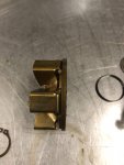
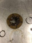
Please look at the picture of the weight basked and see what you think, it appears to have a metal ring on the back instead of the rivet heads and flexible retainer ring.IMG_0548.jpgIMG_0547.jpg
 

Guyfang

Moderator
Staff member
Moderator
16,779
24,115
113
Location
Burgkunstadt, Germany
If the plungers were stuck, that could have been the problem. The crud is not helping.

Can not have come from the army this way. Most of the time we got new pumps, and the old one went back to the manufacturer. The ones we got from the German rebuild shop in K-town, looked better then the new pumps, and always worked right.

The weight basket doesn't look like the ones I have seen. And again, its been a LOOOOOOOOOOOOOOONG time since I looked. But it just doesn't ring a bell in my head.

The fuel shut off lever has to be locked down, to allow the cable to work. The reason you have the second arm is to allow you to use a, hyd actuator, (something probably few people in the forum have seen, unless they are as old as me) and a electronic actuator. Slightly newer, but rarely seen, they were precise gen sets. Mostly ADA units had them, and in 400 hertz gen sets.
 

Ray70

Well-known member
2,595
5,914
113
Location
West greenwich/RI
So what I found is that the weight basket is a newer "1-piece" replacement, not the original with the flexible ring riveted on the back. So more evidence that someone has been in there before.
The plungers were stuck tight in the head. It took 2 days of soaking in carb clean and 140 psi. of air blown down the center ( with all escape holes blocked ) to get 1 to move, then I was able to pop the opposing side out with a brass punch.... but now they are out and everything is cleaned up.
The head is back together, lubed up and roller spacing set to 1.9640"
Just waiting for the rebuild kit to arrive so I have gaskets to assemble the rest.
 

Ray70

Well-known member
2,595
5,914
113
Location
West greenwich/RI
Well, the pump is rebuilt. Made a few mistakes along the way that caused me to have to back up a couple steps, fix, then continue. But all in all it was pretty easy. As soon as I get time I'll reinstall and see if she will fire up!. The stuck plungers were without a doubt the reason it wasn't pumping any fuel.
 

Guyfang

Moderator
Staff member
Moderator
16,779
24,115
113
Location
Burgkunstadt, Germany
Keep in mind, and I think its even written in the TM, that when you time the pump and put it in, if it doesn't start, your probably 180 out. Simply unbolt the IP and slide it back. Turn the pump until the lines match again. and re bolt it up. The bracket up above, that holds all the injector lines in place, needs to be removed, to allow you to pull the pump back. Yeah, you need to unhook a few other things, but not the whole enchilada. Use a good dab of grease on the "seals", on the shaft. Often, sliding the IP in, causes the first seal to flip over. If the oil level increases and the oil smells of diesel, that's what happened. The seals used to be leather, back in the day. But may now be another material. Each fuel line, has two metal seals. They only go one way on, or you leak. I never reused them unless its was a job where the thing had to run, right now. I always replaced them. Cheap insurance.
 

Ray70

Well-known member
2,595
5,914
113
Location
West greenwich/RI
Good advise Guy.... wish I read it before I installed it! I put it in yesterday and it runs! but I've got 2 issues to contend with. There is a very big fuel leak when running ( possibly an injector line seal as you mentioned ( I didn't know they only go in 1 direction ) The good news is that I reused the old ones, so I have a new set in the seal kit that I can use. The other issue is that the throttle / governor is not functioning correctly. With the throttle lever pushed in all the way the engine speed is too high and the governor is hunting rapidly. I believe the throttle cable is attached correctly and the stop screws on the throttle lever did not get moved, but need to double check, my first thought is the Droop adjustment knob because the TM said to screw it in 5 rotations into the spring, but that's no where near as far in as it was originally, so that needs to be double checked as well.
At least it runs now! Just needs a little more tweaking to get it right.
 

Ray70

Well-known member
2,595
5,914
113
Location
West greenwich/RI
Finally got around to messing with this thing again yesterday. I took the top cover off and got the governor spring out of the way so I could poke at the governor assy. to ensure it was free and not bound up somehow. Reassembled and confirmed that I could control the engine speed using the outside lever that is normally tied back unless it's a Precise unit.
After a minute of contemplation I decided to back off the droop adjustment knob a bit and Viola! the engine speed came down.
So it turns out that the initial 5 turns into the spring that the TM recommends puts too much force on the spring for the governor weights to be able to overcome, essentially leaving the pump stuck on full throttle.
Now it's running properly, so I can move on with setting the throttle stops, testing it and getting the droop adjustment dialed in.
You learn something new every day with these things!
 

Ray70

Well-known member
2,595
5,914
113
Location
West greenwich/RI
Well, back to working on this 005 again and looking for some guidance. I had it running fine after rebuilding the IP. I started it the other day and it ran for about 5 seconds and shut off. While troubleshooting it I'm noticing a few odd things.

1) At first it seemed no fuel was flowing from the Day tank / filters to the IP, although the slow pump clicking seemed to indicate the day tank was full. I removed the last filter and had fuel flowing to it so I reassembled it and now seems ok.

2) while working on the IP I noticed that sometimes I would have fuel pumping from the return line to the IP ( if I have the line disconnected and run the fuel pump ) and sometime not. Could someone please explain the function of the solenoid valve where the return line and fuel inlet to the day tank merge?

3) Occasionally the fuel pump will run a very long time before clicking slows almost to a stop, almost as if fuel is not pumping into the day tank or the float is sticking and allowing fuel to overfill and back down the vent lines?

4) I removed the end cap on the IP to take a look at the pump vanes and verify fuel input and had fuel and pump looks fine, but even after cranking a while I still don't have any fuel up top in the upper cavity of the IP where the solenoid is. Previously this cavity would slowly fill up just from gravity feed from the day tank.
I'm starting to think I now have a problem within the IP again, possibly something with the vane pump on the back of the IP.
 

Guyfang

Moderator
Staff member
Moderator
16,779
24,115
113
Location
Burgkunstadt, Germany
Well, back to working on this 005 again and looking for some guidance. I had it running fine after rebuilding the IP. I started it the other day and it ran for about 5 seconds and shut off. While troubleshooting it I'm noticing a few odd things.

1) At first it seemed no fuel was flowing from the Day tank / filters to the IP, although the slow pump clicking seemed to indicate the day tank was full. I removed the last filter and had fuel flowing to it so I reassembled it and now seems ok.

2) while working on the IP I noticed that sometimes I would have fuel pumping from the return line to the IP ( if I have the line disconnected and run the fuel pump ) and sometime not. Could someone please explain the function of the solenoid valve where the return line and fuel inlet to the day tank merge?

3) Occasionally the fuel pump will run a very long time before clicking slows almost to a stop, almost as if fuel is not pumping into the day tank or the float is sticking and allowing fuel to overfill and back down the vent lines?

4) I removed the end cap on the IP to take a look at the pump vanes and verify fuel input and had fuel and pump looks fine, but even after cranking a while I still don't have any fuel up top in the upper cavity of the IP where the solenoid is. Previously this cavity would slowly fill up just from gravity feed from the day tank.
I'm starting to think I now have a problem within the IP again, possibly something with the vane pump on the back of the IP.


Ray,
Here is how the whole thing functions.
1. When the S2 is in the start position, or
2.S2 in the run position, (engine NOT running) and the S7 is flipped up, or
3. S2 in the run position, (engine running)

your two electric fuel pumps, (B2 & B3) are energized. And they stay energized. At some point in time, (hopefully) the day tank fills up. When that happens, the FL2, (day tank fuel level switch) opens its contacts. That cuts voltage off to the L2, (day tank solenoid) and the L2 closes. When that happens, the B2 and B3 continue to pump, but fuel will NOT be delivered to the day tank because L2 is closed. The B2 and B3 cannot compress the fuel, nor pump it further, so they slow down or stop. The system stays that way, until the fuel level in the day tank drops far enough for the FL2 contacts to close again, allowing the L2 to reopen and fuel is replenished again in the day tank.

1) At first it seemed no fuel was flowing from the Day tank / filters to the IP, although the slow pump clicking seemed to indicate the day tank was full. (The fuel in the day tank is not under pressure. Its gravity flow after the day tank. Also, there are times when the FL2 can malfunction, and tell the L2 to close. Then it stops the fuel flow. The day tank may be empty, or say partly full. Your CR-27 could also be a part of this problem.) I removed the last filter and had fuel flowing to it so I reassembled it and now seems ok.

2) while working on the IP I noticed that sometimes I would have fuel pumping from the return line to the IP ( if I have the line disconnected and run the fuel pump ) and sometime not. (See above) Could someone please explain the function of the solenoid valve where the return line and fuel inlet to the day tank merge? (The "return line" is there to keep the day tank safe, should FL2 be closed, and not be able to open, and to give you a place to hook up the diesel fired heater used on this set. The tank cannot over fill. In theory.)

3) Occasionally the fuel pump will run a very long time before clicking slows almost to a stop, almost as if fuel is not pumping into the day tank or the float is sticking and allowing fuel to overfill and back down the vent lines? (This could be happening. FL2 sticks/hangs up. Common problem.)

4) I removed the end cap on the IP to take a look at the pump vanes and verify fuel input and had fuel and pump looks fine, but even after cranking a while I still don't have any fuel up top in the upper cavity of the IP where the solenoid is. Previously this cavity would slowly fill up just from gravity feed from the day tank. (This should not happen. L1, (engine fuel shut off solenoid) Should only let fuel through when its energized. When cranking, the L1 SHOULD be energized, and fuel should be entering the IP. If not, then the L1 is not energized, or stopped up, or there is no fuel in the inlet line to the IP. This could indicate that you have a problem with dirt/trash in the check valve above the L1, or perhaps the diesel varnish has caused the check valve to not work right.

First thing I would do is check FL1 and FL2. The test procedure in the TM is easy, and its not hard to get at. First, drain half the fuel out of the Day Tank, using the petcock on the bottom of the day tank. Then I just pulled the float switch out, re-hooked up the J33/P33 canon plug, place the S2 in the run position and the S7 in the up position. WARNING WILL ROBINSON! WARNING!! Turn the float switch upside down. That way it is in the full position. Have someone else turn S2 and S7 on. As long as the float switch is good, and turned upside down, life is good. Should you decide to let go of the switch and go get a beer, and the S2 and S7 are on, in about a few seconds, the day tank WILL over fill. It makes a real big mess, in a real short time. So, back to the quick and dirty test. With the float switch in your one hand, move the float with the other. Since its upside down, move the float a bit, and the B2 and B3 should come on. Move it back, they should cut off. Move it once again up, the B2 and B3 come on, and move it farther, and the FL1 should open up and the K8 is going to send you a red light on the A9, (fault indicator) AND cut power to L1, to stop the gen set from running out of fuel.

While you are fooling with the float switch, you can also check CR-27. Again, easy to check/test. Its in the TM. The same for the L2. There are several different types of float switches. The old one had two floats on the rod. The newer one only has one float. There are magnets embedded in the float material. That's what opens and closes the FL1 and FL2 contacts. The float switches were a weak point in the set. According to CECOM, they "work better now". Look to see if the magnets are in the float. Sometimes the float material crumbles away, and the magnet fall out. Lots of times the float gets stuck, or goes up and down erratically.
 

Ray70

Well-known member
2,595
5,914
113
Location
West greenwich/RI
Hello Guy, well.... decided to get back to fixing the 005 this week. I pulled off the IP and first found the inner shaft seal was folded over allowing fuel to leak into the oil pan. I went through the pump again and didn't really find anything out of order, so reassembled and installed it. I'm getting fuel from the day tank to the IP but I am not getting anything out to the injectors and I'm pretty sure I am not getting transfer pump pressure. I paid close attention to the vane pump eccentric, thrust plate and the check / relief valve and found nothing wrong. I've verified the fuel solenoid is functioning correctly, but still nothing.
The one thing I did not check while the IP was apart was the calibrated vent wire. I was unable to remove the screw, so I did what I could to clean the passages with carb cleaner. If I remove the side window from the pump I have fuel in the pump housing.
So to recap, last year I rebuilt the pump and had it running, but one day it started, ran for 10 seconds then stopped and hasn't run since.
I'm wondering what your thoughts are on the possibility of a clogged vent wire passage or the shaft seal preventing me from getting transfer pump pressure? As I mentioned before, originally the upper cavity and entire pump would be filled with fuel, now I'm only getting fuel about 1/2 way up the timing inspection window.... curiously this is about the level where a leaking shaft seal would probably drain fuel into the oil.
 
Top
AdBlock Detected

We get it, advertisements are annoying!

Sure, ad-blocking software does a great job at blocking ads, but it also blocks useful features of our website like our supporting vendors. Their ads help keep Steel Soldiers going. Please consider disabling your ad blockers for the site. Thanks!

I've Disabled AdBlock
No Thanks