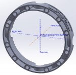
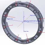
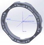
Looks like a good plan. Don't know if you plan to design it with all the mounting holes but if it is strong enough then it would seem like we would only need the eight to hold in the cross and gears. Believe when setting up the hub we could remove the cross O rings for the set up and replace them when ready for final install of the real hub. Just another thought. Could you just do half of that mold. Would be nice to be one piece but installing two pieces to hold in all four point of the cross would still work.
I think we're thinking the same thing. Are you saying that since we probably only need to use the holes marked in red, I'm free to cut away at the unmarked holes to get it to fit on the printer?
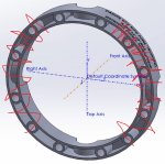
I only need to knock 0.2" minimum off, or something like 0.5-0.75" would be better. That looks about like this below. So if I remove those holes at each 45° (which would get cut), and rebuild the outer wall for strength, it should be ok. That's what my plan currently is.
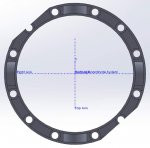
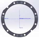
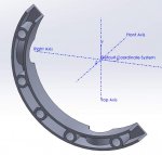
I'm interpreting your other suggestion as cutting it into two pieces, in order to only have the minimum necessary to hold the cross in place. That would look something like this below roughly, and you would need QTY 2. I hadn't really considered that (mostly because the above would work on my printer), but it's certainly not hard to do, for those that have much smaller printers.
I was asked...
What tolerances do we really need on the radius and surface of the semi-circular cutouts?
- I'm not sure what tolerances we really need on the semi-circular cutouts. The way I designed this, I drew one circle that is exactly the size I measured from the real metal cover that I have, then I drew a circle 0.005" bigger and used that larger circle to make the cutout in my model. The reason for that is I now have introduced a 0.005" tolerance (so my printer could print the cutout 0.005" too small and it would be exactly the size of my metal cover). Every printer is going to be a little different, but it gives me the ability to go in the model and adjust that 0.005" to tweak the results we're getting, without messing with the inner circle diameter which is the real target.
What about the tolerances on the height from the base to the semi-circular cutouts?
- I'm not sure what the tolerance on the height of those cutouts is either. When I measured the cutouts with good calipers, and averaged between the 4 cutouts, the number I came up with was within 0.001" of 32mm. So I'm assuming the true diameter of that cross pin is 32mm. Then, when I measured the depth of the cutouts, and averaged, I was again within 0.001" of it being 15mm deep. On one hand, that number makes sense, 15mm is half of 30mm. On the other hand, I expected it to be slightly less than 15mm to account for the thickness of a gasket. But I guess it works just fine at 15mm deep, so we'll roll with it for now. If we're having problems holding the cross pins down, it's an easy thing to adjust.
