Larry Weibert
Active member
- 102
- 120
- 43
- Location
- Youngstown New York
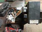
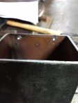
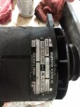
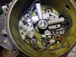
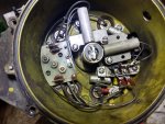
Hi Guys, So My dump isn't charging. LEECE -NEVILLE A001 3002 AE 60 Amp alt. Ill explain what I did and hopefully some one can help out a bit. I started by reading the TM related to the charging system. Test 3 & 4 which is power is present to the wire at the alt with ign switch On and test 4 which is testing at the control box on the firewall. That test lead to the control box being bad. I opened the control box see the pics. Very easy to break the solder joint then drill the two spot welds and she opens up. I tested all components and the silver relay tested bad I believe a contact broke internally so I ordered a new one to repair the control box. A new box looks like $ 400 so the repair looks like $20.
I took the control box off my other 800 series truck installed it and repeated test 4 which showed the control box ok but then lead me to test for continuity from the control box to the output lead of the alt. That tested ok so the chain said something with the alt is bad.
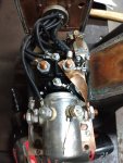
Ok I removed the alt. Pulled the reg off the back ( see the pic ). I tested the many things which all checked out. I then talked to Tom at Southern Automotive Wholesalers Inc he is very knowledgeable. After explaining all I tested internally to the alt he said run jumpers to the brushes and reinstall the alt without the regulator. start the truck and apply 24v to the leads and see what the voltage is and If the idle changes meaning its charging. I obviously unhooked the leads to the terminal block so in this test the comm wasn't shorted together. It worked 28.8 volts so he said probably changing the regulator and I should be all set.
I ordered reg 2920-01-079-9130 which he gave me the number as his company sells there military overstock them on ebay.
Ok so here is my issue. I noticed that the brushes have a two brush holders. One has one brush and the other has two brushes. Its a little hard to see from the pick but the one on the right has a second brush behind the front one. I noticed that every wire labels 1-5 left to right on the terminal block.
The one brush on the left was on term 3 as labled. The other one above it comes from the right back brush and is labeled 3 and on the stud above the other but going to the right hand back brush meaning the two commutators are shorted together I believe.
My shop manager who has 40 years experience in the field thought 3 & 4 on the lower terminals needed to be swapped. I don't want to install the new reg when it comes in and have it wrong. I cant seem to find a TM with a view that shows the placement. All the wires are labeled and placed as stated but I don't see how it could work if you short the commutators together through the brushes. Any help is appreciated.
Attachments
-
3.8 MB Views: 11
-
3.5 MB Views: 11
-
3.9 MB Views: 11
-
3.5 MB Views: 11
-
3.6 MB Views: 11
Last edited:


