• Steel Soldiers now has a few new forums, read more about it at: New Munitions Forums!

  • Microsoft MSN, Live, Hotmail, Outlook email users may not be receiving emails. We are working to resolve this issue. Please add support@steelsoldiers.com to your trusted contacts.

MEP005A 5volts only

pf.hal1984

Member
48
25
18
Location
Killeen Tx
So I was recently tasked to get this generator working. I only get 5 volts from the 120ac power outlet when I'm holding the start switch and maxing out generator speed. 50hz on the gauge. Once i release the start switch everything goes back to 0. The batteries are not charging as well. It runs perfect. I'm leaning towards the voltage regulator/excitor. If it is this part, what exact part would go out in it to cause neither side to generate power?
 

pf.hal1984

Member
48
25
18
Location
Killeen Tx
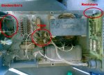
So here is what I got. On the A5 circuit board Resistor R3 looks burnt. 5905-00-357-3093 resistor is not available anywhere along with A5 board 6110-00-201-6015 . Would anyone have any information on where to find these parts?
 

kloppk

Well-known member
Steel Soldiers Supporter
2,149
3,533
113
Location
Pepperell, Massachusetts
Looks like it's a 1.5 Kohm 10 Watt wire wound resistor.
Length 1.78"
Diameter 0.375"

Digikey has one that match's the specs above.
Resistor

Manufacturer Vishay Dale
Series RS
Packaging Cut Tape (CT)
Part Status Active
Resistance 1.5 kOhms
Tolerance ±1%
Power (Watts) 10W
Composition Wirewound
Features Moisture Resistant
Temperature Coefficient ±20ppm/°C
Operating Temperature -65°C ~ 250°C
Package / Case Axial
Supplier Device Package Axial
Size / Dimension 0.375" Dia x 1.780" L (9.53mm x 45.21mm)
 

Guyfang

Moderator
Staff member
Moderator
16,787
24,129
113
Location
Burgkunstadt, Germany
This is a very normal fault with this set. Before replacing R3, and installing the SP/Relay box, do check K7, and CR4. Its easy. apply 120 volts on pins A5-18, and A5-22. You should hear and feel the K7 click as it opens and closes its contacts. Open up TM9-6115-464-12, to PDF reader page #338. At the top right corner is a schematic for the A5 card. You can also test K7 when its not plugged into the A5. Its in the TM also. If you cant find it, say something and I will post something. Like Kurt posted, its a stink normal resister. Easy to replace.
 

pf.hal1984

Member
48
25
18
Location
Killeen Tx
This is a very normal fault with this set. Before replacing R3, and installing the SP/Relay box, do check K7, and CR4. Its easy. apply 120 volts on pins A5-18, and A5-22. You should hear and feel the K7 click as it opens and closes its contacts. Open up TM9-6115-464-12, to PDF reader page #338. At the top right corner is a schematic for the A5 card. You can also test K7 when its not plugged into the A5. Its in the TM also. If you cant find it, say something and I will post something. Like Kurt posted, its a stink normal resister. Easy to replace.
I will do just that but one question before I break out my laptop. 120v or 12v?
 

peapvp

Well-known member
Steel Soldiers Supporter
1,118
1,243
113
Location
Basehor, KS
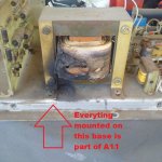
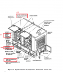
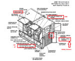
Next thing would be to check A11.

The Relay on A5 is operated by 120VAC through a bridge rectifier and a resistor as voltage step down to 24VDC
 

pf.hal1984

Member
48
25
18
Location
Killeen Tx
I assumed that the A11 would be the issue when I first assessed the generator. I also assume that the K5 relay on the A5 card is an issue because both battery generation and the generator set itself have power supplied to through this relay. The schematics I look at tell me nothing to look for. Any hints?
 

peapvp

Well-known member
Steel Soldiers Supporter
1,118
1,243
113
Location
Basehor, KS
pf.hal1984,

The most common issue with those Genset's is as follows:

At one point Genset does no longer produce Output Power. At first, if the Voltage Regulator in the A11 is OK, the Genset will excite the Output on the Volt Gauge up to 120 VAC as long as S1 is held in start position. If the Voltage on the Volt Gauge does not increase while in start then two issues need to be checked.
1. Does the S9-1 speed switch closes and activates K5 after reaching app. 600 to 900 rpm?
2. If it does and volt gauge shows voltage then Capacitor C2 and Transformer T2 in A11 have to be checked - C2 ages and eventually fails causing T2 to burn out
3. If it does not show Voltage then the two SCR's on the Voltage Regulator Card are probably toast, besides this C2 is probably due for a change too and hopefully T2 hasn't burnt out yet
4. There is a remote issue that the connections between A11, Cubilcle and Relay box are corroded, loose or disconnected
5. You may want to check resistance on your exciter coil

A11 full.jpg

a11closeup3.jpg

exciter6.jpg

004A view1.png
004A view2.png

J13.png

70646765_3353805217993796_2762315977428303872_n.jpg


I assumed that the A11 would be the issue when I first assessed the generator. I also assume that the K5 relay on the A5 card is an issue because both battery generation and the generator set itself have power supplied to through this relay. The schematics I look at tell me nothing to look for. Any hints?
 

pf.hal1984

Member
48
25
18
Location
Killeen Tx
pf.hal1984,

The most common issue with those Genset's is as follows:

At one point Genset does no longer produce Output Power. At first, if the Voltage Regulator in the A11 is OK, the Genset will excite the Output on the Volt Gauge up to 120 VAC as long as S1 is held in start position. If the Voltage on the Volt Gauge does not increase while in start then two issues need to be checked.
1. Does the S9-1 speed switch closes and activates K5 after reaching app. 600 to 900 rpm?
2. If it does and volt gauge shows voltage then Capacitor C2 and Transformer T2 in A11 have to be checked - C2 ages and eventually fails causing T2 to burn out
3. If it does not show Voltage then the two SCR's on the Voltage Regulator Card are probably toast, besides this C2 is probably due for a change too and hopefully T2 hasn't burnt out yet
4. There is a remote issue that the connections between A11, Cubilcle and Relay box are corroded, loose or disconnected
5. You may want to check resistance on your exciter coil

View attachment 787711

View attachment 787712

View attachment 787714

View attachment 787715
View attachment 787716

View attachment 787717

View attachment 787718
Very detailed. Thank you. The only issue I found is R2 has 52 ohms which states it should be 510. R3 has 498 ohms which should be 510. Both my transformers are good with no resistance across the H and Xs. Would R2 be my issue?
 

peapvp

Well-known member
Steel Soldiers Supporter
1,118
1,243
113
Location
Basehor, KS
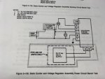
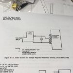
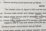
The only way you can tell for sure if the A11 is OK or not by doing the 3 tests outlined in the TM Number is this picture

A11 full.jpg

69635497_2143592525940825_8041945435599798272_n.jpg

69879143_390929688291112_1481531020086870016_n.jpg

69831663_2134225606886568_1674985319285391360_n.jpg69851708_2390397721176733_4875557564869246976_n.jpg


Very detailed. Thank you. The only issue I found is R2 has 52 ohms which states it should be 510. R3 has 498 ohms which should be 510. Both my transformers are good with no resistance across the H and Xs. Would R2 be my issue?
 

Guyfang

Moderator
Staff member
Moderator
16,787
24,129
113
Location
Burgkunstadt, Germany
Stop. Before you get ahead too far.

Go back to post 14. Peter asked you if the S9-1 contacts had been made. That has to happen for K5 to light off the main gen. Have you checked the S9-1 contacts. There are NOT, just one set, there are two sets of contacts. One set allows the starter to engage, and then kicks it out, at approx 580-620 RPM. When this happens, and the contacts open, (pins A&B on the S9) another set CLOSES, energizing K5, (pins A&C, if I remember right).
 

pf.hal1984

Member
48
25
18
Location
Killeen Tx
Stop. Before you get ahead too far.

Go back to post 14. Peter asked you if the S9-1 contacts had been made. That has to happen for K5 to light off the main gen. Have you checked the S9-1 contacts. There are NOT, just one set, there are two sets of contacts. One set allows the starter to engage, and then kicks it out, at approx 580-620 RPM. When this happens, and the contacts open, (pins A&B on the S9) another set CLOSES, energizing K5, (pins A&C, if I remember right).
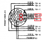
How do I test this? I know it turns off the starter. I get 5v out the accessory plug and shows about 25v on the gauge only when I hold it in start and at full throttle. I'm thinking about adding a switch to jump A and C. I put my finger on K5 but I can't tell if it is K7 next to it operating.
 
Last edited:
Top
AdBlock Detected

We get it, advertisements are annoying!

Sure, ad-blocking software does a great job at blocking ads, but it also blocks useful features of our website like our supporting vendors. Their ads help keep Steel Soldiers going. Please consider disabling your ad blockers for the site. Thanks!

I've Disabled AdBlock
No Thanks