• Steel Soldiers now has a few new forums, read more about it at: New Munitions Forums!

  • Microsoft MSN, Live, Hotmail, Outlook email users may not be receiving emails. We are working to resolve this issue. Please add support@steelsoldiers.com to your trusted contacts.

MEP005A 5volts only

peapvp

Well-known member
Steel Soldiers Supporter
1,118
1,243
113
Location
Basehor, KS
pf.hal1984

Please check the resistance of your exciter coil in the genhead first

a) Locate this barrier terminal strip with two positions:
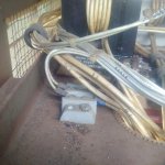
terminal.jpg

locate and remove wire F1 and F2 - check ohm between these two - should be between 1 to 4 ohm

remember which F wire goes to which terminal

then proceed as follows:

b. Equipment Test of Field Flash Circuit Assuming the exciter stator winding resistance is correct (within 1 to 4 ohms)Connect a DC voltmeter (0 to 30 volts) to the two wires that are disconnected from the exciter stator windings. NOTE DO NOT reconnect the wires to leads F1 and F2 at this time.

c. Remove Connector P37 from speed switch. Place a jumper between pins A and C on P37. Momentarily,approximately 10 to 15 seconds, place the START-STOP-RUN switch in the START position and observe the DCvoltmeter. If the voltmeter indicates approximately 24 volts, the probable cause of the field flash is the speed switch. If aDC voltmeter is not available, proceed to step d.

d. Remove Connector P3 from the speed switch. Place a jumper between pins A and C of socket J3 on the specialrelay box for approximately 24 volts DC. If a DC voltage is not present, the problem may be the wiring between the speedswitch and the special relay box, the K5 relay, or current limiting resistor (R35) inside the special relay box (15kW and 30kW generator sets only). If a DC voltage is present, replace Connector P3 on socket J3 and proceed to the next step.

e. Remove Connector P9 from the static exciter/voltage regulator control box. Momentarily, hold the START-STOPRUNswitch in the START position and check between pins C and D of P9 for approximately 24 volts DC. If a DC voltageis not present, the problem may be the wiring between the special relay box and the static exciter/voltage regulator controlbox. If a DC voltage is present, replace Connector P9 on-socket J9 and’ proceed to the next step.

f. Remove Connector P13 from the static exciter/voltage regulator control box. Momentarily, hold the STARTSTOP-RUN switch in the START position and check between pins S and R of J13 on the control box for approximately 24volts DC. If a DC voltage is not present, the problem may be any one of the following items within the control box:

(1) Broken wire within the control box.
(2) Current limiting resistor R219 sets.
(3) Current limiting resistor R17 sets.

g. Reconnect the wires previously removed from the exciter field winding, F1 and F2.
 

Guyfang

Moderator
Staff member
Moderator
16,789
24,129
113
Location
Burgkunstadt, Germany
Peter, something wrong here. Look at step d. The S) only has one plug, and that's P37. If I was in front of my computer, would look at what I assume you mean is the cable from the S9 to A27 SP/Relay box.
 

peapvp

Well-known member
Steel Soldiers Supporter
1,118
1,243
113
Location
Basehor, KS
Peter, something wrong here. Look at step d. The S) only has one plug, and that's P37. If I was in front of my computer, would look at what I assume you mean is the cable from the S9 to A27 SP/Relay box.
Guy, this is straight out of the maintenance manual, but you are probably correct, meaning to remove P37
 

peapvp

Well-known member
Steel Soldiers Supporter
1,118
1,243
113
Location
Basehor, KS
Clarification:

I double checked the manual and wiring diagram and d) should read as follows:

d. Remove Connector P3 from J3 on the special relay box. Place a jumper between pins A and C of socket J3 on the special relay box for approximately 24 volts DC. If a DC voltage is not present, the problem may be the wiring between the speed switch and the special relay box, the K5 relay, or current limiting resistor (R35) inside the special relay box (15kW and 30kW generator sets only). If a DC voltage is present, replace Connector P3 on socket J3 and proceed to the next step.

P37 itself remains connected to the speed switch. I guess this clarifies the issue.
 

pf.hal1984

Member
48
25
18
Location
Killeen Tx
So I followed those steps out of the TM originally. Jumped A and C and I have voltage. Originally I don't think my test points were in the correct spots but that was a while ago. Being that I get 24 volts where the exciter wires go. It states that if I get voltage when jumped I'm looking at a bad speed sensor. What spot on the A5 board could I wire a switch to?
 

peapvp

Well-known member
Steel Soldiers Supporter
1,118
1,243
113
Location
Basehor, KS
pf.hal1984,

Can we assume that you measured the resistance between F1 and F2 and it checked out OK ( 1 to 4 Ohms)?


So I followed those steps out of the TM originally. Jumped A and C and I have voltage. Originally I don't think my test points were in the correct spots but that was a while ago. Being that I get 24 volts where the exciter wires go. It states that if I get voltage when jumped I'm looking at a bad speed sensor. What spot on the A5 board could I wire a switch to?
 

Guyfang

Moderator
Staff member
Moderator
16,789
24,129
113
Location
Burgkunstadt, Germany
So I followed those steps out of the TM originally. Jumped A and C and I have voltage. Originally I don't think my test points were in the correct spots but that was a while ago. Being that I get 24 volts where the exciter wires go. It states that if I get voltage when jumped I'm looking at a bad speed sensor. What spot on the A5 board could I wire a switch to?
Why do you want to wire a switch to it?
 

Guyfang

Moderator
Staff member
Moderator
16,789
24,129
113
Location
Burgkunstadt, Germany
I'm probably going to tap into A and C and add a remote switch to the control board.
Not necessary. There is 24 volts every place in the A27. You can just then go from there to pin A5-13.

Or, much better idea,

Hook everything back up. leave the bottom part of A27 off. Hook a wire to A5-13, long enough to come out of the A27 and have a few feet to play with. With every thing hooked back up, and I mean everything, start the set. When it runs, and will not produce voltage, take the wire hanging out of the A27, and touch it to the big terminal attached to the starter. The POSITIVE terminal.

In fact, do everything I just wrote above. Before you start the set, hook a multimeter to the wire hanging out of the A27. Then measure for 24 volts on start up. If you do NOT get the 24 volts, THEN touch the wire from A27 to the hot terminal. Have someone else watch the volt and hertz meter to see if it comes up.

Now, if you intend to LEAVE a perminit wire hooked up to a switch, so you can run this set without getting a S9 switch to replace the one that MIGHT be broken, do not get upset when something bad happens to your gen set. There is a reason the S9 is there. What I have outlined above, is for testing. NOT to be used for ever.
 

pf.hal1984

Member
48
25
18
Location
Killeen Tx
Not necessary. There is 24 volts every place in the A27. You can just then go from there to pin A5-13.

Or, much better idea,

Hook everything back up. leave the bottom part of A27 off. Hook a wire to A5-13, long enough to come out of the A27 and have a few feet to play with. With every thing hooked back up, and I mean everything, start the set. When it runs, and will not produce voltage, take the wire hanging out of the A27, and touch it to the big terminal attached to the starter. The POSITIVE terminal.

In fact, do everything I just wrote above. Before you start the set, hook a multimeter to the wire hanging out of the A27. Then measure for 24 volts on start up. If you do NOT get the 24 volts, THEN touch the wire from A27 to the hot terminal. Have someone else watch the volt and hertz meter to see if it comes up.

Now, if you intend to LEAVE a perminit wire hooked up to a switch, so you can run this set without getting a S9 switch to replace the one that MIGHT be broken, do not get upset when something bad happens to your gen set. There is a reason the S9 is there. What I have outlined above, is for testing. NOT to be used for ever.
Ok it's definitely not the speed switch. I get 24v to 13 when held in start. K5 clicks even with my remote switch.
 

peapvp

Well-known member
Steel Soldiers Supporter
1,118
1,243
113
Location
Basehor, KS
You need to get 24 V on the two terminals where F1 and F2 connect to when K5 is activated.
This should be tested with F1 and F2 disconnected from these two terminals

Ok it's definitely not the speed switch. I get 24v to 13 when held in start. K5 clicks even with my remote switch.
 

Guyfang

Moderator
Staff member
Moderator
16,789
24,129
113
Location
Burgkunstadt, Germany
Roger. What do you get at F1 and F2. Hook it all back up and unhook F1 and F2. Hook the multimeter to F1 and F2, looking for 24 volts. have someone else start the set, and you mind the meter.
 

peapvp

Well-known member
Steel Soldiers Supporter
1,118
1,243
113
Location
Basehor, KS
Guy, his resistance on F1 and F2 is 2 Ohm, which is within spec.
So, exciter coil seems to be OK

Roger. What do you get at F1 and F2. Hook it all back up and unhook F1 and F2. Hook the multimeter to F1 and F2, looking for 24 volts. have someone else start the set, and you mind the meter.
 

peapvp

Well-known member
Steel Soldiers Supporter
1,118
1,243
113
Location
Basehor, KS
Guy, "Hook it all back up and unhook F1 and F2."

How would he get 24V on F1 and F2 if they are disconnected from the Terminal Block? Those are the two wires into the Genset Head

Roger. What do you get at F1 and F2. Hook it all back up and unhook F1 and F2. Hook the multimeter to F1 and F2, looking for 24 volts. have someone else start the set, and you mind the meter.
 
Top
AdBlock Detected

We get it, advertisements are annoying!

Sure, ad-blocking software does a great job at blocking ads, but it also blocks useful features of our website like our supporting vendors. Their ads help keep Steel Soldiers going. Please consider disabling your ad blockers for the site. Thanks!

I've Disabled AdBlock
No Thanks