patrol578
Member
- 107
- 22
- 18
Howdy folks.
In the interest of providing some passive moderation to the FLU419 discussions here, I'd like to start a thread on SEE transmission specifics, and trans issues owners may have had. Hopefully we can start divvying up the various systems into their own threads, rather than just dumping it all in the SEE Owners Forum thread (I admit to being just as guilty as anyone). Up to this time, I have found a good bit of transmission information here at Steel Soldiers, but it is scattered among ambiguous threads with names like "My SEE Won't Move, HELP," as well as the ungainly Owners Forum (was it Peakbagger that called it monstrous a while back?).
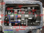
So, without further yakking, here is my first contribution, an annotated image taken from above the trans with the top cover removed. It is courtesy of choprboy over on Benzword. I have literally spent days poring over the Army TMs trying to figure out how it all goes together and works. Choprboy's picture helped me understand it all in just a few minutes.

Left is the front of the truck, right is rear, top is passenger side, bottom is driver's. Here's how the power flows:
Power comes in from the airshift cascade gearbox via the Input Shaft. In LOW (forward) RANGE and REVERSE, it follows the blue line, spinning the Reduction Shaft.
The Reduction Shaft turns the Main Shaft or the Counter Shaft (depending on the position of the Forward/Reverse collar). In LOW it spins the Main Shaft via the 3rd gear. The Main Shaft then spins the Counter Shaft (in gears 1, 2 and 3, but not 4th). The Counter Shaft turns that giant gear on the far right which is fixed to the Output Shaft. But in REVERSE the Reduction Shaft turns the 2nd gear cog riding on (but not fixed to) the Counter Shaft. That 2nd gear cog then turns the Main Shaft and power runs through gears 1/3/4 as normal. When in 2nd gear, the gear cog is then fixed to the Counter Shaft and spins the Output Shaft directly (without going through the Main Shaft).
The Output Shaft is connected to the rear prop shaft by a flange. The front prop shaft is driven by spur gears which take power from that giant gear on the Output shaft. The first of these is just visible at the very bottom right of the image.
In HIGH RANGE (II on the shuttle lever) the High Range collar couples the Input Shaft to the Main Shaft and power follows the green line. The Forward/Reverse collar on the Reduction Shaft remains in Neutral.
In 4th gear (regardless of shuttle lever position), the 4th gear collar couples the Main Shaft to the Output Shaft. So in II/4th, the Output Shaft is directly driven at the same RPM as the Input Shaft brings into the gearbox. Although it looks like the Input, Main and Output shafts are all one and the same, they actually spin independently of each other unless the High Range or 4th Gear collars are engaged.
My next post will be a similar one about the workings of the shifting mechanisms found on the underside of the transmission top cover. If I have made any mistakes on the above, PLEASE call me out so that I can make the correction. Choprboy, if you are lurking here, feel free to correct me on B-world if I've screwed anything up, and big thanks for the annotated picture!
Hope this helps,
Patrol578
In the interest of providing some passive moderation to the FLU419 discussions here, I'd like to start a thread on SEE transmission specifics, and trans issues owners may have had. Hopefully we can start divvying up the various systems into their own threads, rather than just dumping it all in the SEE Owners Forum thread (I admit to being just as guilty as anyone). Up to this time, I have found a good bit of transmission information here at Steel Soldiers, but it is scattered among ambiguous threads with names like "My SEE Won't Move, HELP," as well as the ungainly Owners Forum (was it Peakbagger that called it monstrous a while back?).
So, without further yakking, here is my first contribution, an annotated image taken from above the trans with the top cover removed. It is courtesy of choprboy over on Benzword. I have literally spent days poring over the Army TMs trying to figure out how it all goes together and works. Choprboy's picture helped me understand it all in just a few minutes.

Left is the front of the truck, right is rear, top is passenger side, bottom is driver's. Here's how the power flows:
Power comes in from the airshift cascade gearbox via the Input Shaft. In LOW (forward) RANGE and REVERSE, it follows the blue line, spinning the Reduction Shaft.
The Reduction Shaft turns the Main Shaft or the Counter Shaft (depending on the position of the Forward/Reverse collar). In LOW it spins the Main Shaft via the 3rd gear. The Main Shaft then spins the Counter Shaft (in gears 1, 2 and 3, but not 4th). The Counter Shaft turns that giant gear on the far right which is fixed to the Output Shaft. But in REVERSE the Reduction Shaft turns the 2nd gear cog riding on (but not fixed to) the Counter Shaft. That 2nd gear cog then turns the Main Shaft and power runs through gears 1/3/4 as normal. When in 2nd gear, the gear cog is then fixed to the Counter Shaft and spins the Output Shaft directly (without going through the Main Shaft).
The Output Shaft is connected to the rear prop shaft by a flange. The front prop shaft is driven by spur gears which take power from that giant gear on the Output shaft. The first of these is just visible at the very bottom right of the image.
In HIGH RANGE (II on the shuttle lever) the High Range collar couples the Input Shaft to the Main Shaft and power follows the green line. The Forward/Reverse collar on the Reduction Shaft remains in Neutral.
In 4th gear (regardless of shuttle lever position), the 4th gear collar couples the Main Shaft to the Output Shaft. So in II/4th, the Output Shaft is directly driven at the same RPM as the Input Shaft brings into the gearbox. Although it looks like the Input, Main and Output shafts are all one and the same, they actually spin independently of each other unless the High Range or 4th Gear collars are engaged.
My next post will be a similar one about the workings of the shifting mechanisms found on the underside of the transmission top cover. If I have made any mistakes on the above, PLEASE call me out so that I can make the correction. Choprboy, if you are lurking here, feel free to correct me on B-world if I've screwed anything up, and big thanks for the annotated picture!
Hope this helps,
Patrol578
Last edited:


