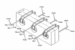
(7) Current Voltage Transformer (CVT1). Using
an ohmmeter check three primary windings of
transformer (figure 1-1, 6-7.1 and 6, figure 6-9) by
measuring resistance from terminals H1 to H2, H3 to
H4, H5 to H6, Resistance must be 2.27 ohms ± O.227
ohms. Check resistance in three secondary windings
of transformer by checking from terminals X1 to X2,
X1 to X3, X2 to X3. Resistance must be 1.68 ohms
±0.168 ohms. Check resistance in control windings by
checking from terminals C1 to C2. Resistance must be
9.6 ohms ± 0.96 ohms. If any of the windings do not
show the proper resistance, replace transformer.
(

Current Transformer (CT1). On the current
transformer (figures 1-1, 6-7.1 and 7, figure 6-9) only
the secondary windings can be checked. Using an
ohmmeter check resistance in secondary windings by
checking from terminals 1A to 2A, 1B to 2B, 1C to 2C.
Resistance must be 0.5 ohms ±0.05 ohms. If any of
the windings do not show the proper resistance,
replace transformer.
(9) Bridge Rectifier Assembly (A4) (see figure
6-11 ). Tag and remove leads to terminal board and to
each diode (3) separately by checking between terminals
(6) shown in table 6-6. Resistance in one direction
should be very high in one direction and very low
in the other. Measure resistance of R1 (4). It should
be 56 ohms.


