• Steel Soldiers now has a few new forums, read more about it at: New Munitions Forums!

  • Microsoft MSN, Live, Hotmail, Outlook email users may not be receiving emails. We are working to resolve this issue. Please add support@steelsoldiers.com to your trusted contacts.

30KW with Diesel Engine/ How to Prime Fuel System/

Lugnuts

Active member
Steel Soldiers Supporter
323
239
43
Location
Myakka City, FL
Gentlemen: About 2 weeks ago I had a generator load up with water on the fuel side/ So I removed filters, drained the injection pump, cleaned the lines and checked my diesel supply ie I cleaned the tank/ So I went to start it and it seems I lost prime and need to replace the quad rings at the filters/ First time I did this job I turned a switch on at the controls under a red cover and held the primer switch. All worked well/ Now I'm not getting the same results when I try to prime it. Please educate me on how to prime these generators or where the fuses are. Thank you, Lugnuts
 

Guyfang

Moderator
Staff member
Moderator
16,766
24,082
113
Location
Burgkunstadt, Germany
Gentlemen: About 2 weeks ago I had a generator load up with water on the fuel side/ So I removed filters, drained the injection pump, cleaned the lines and checked my diesel supply ie I cleaned the tank/ So I went to start it and it seems I lost prime and need to replace the quad rings at the filters/ First time I did this job I turned a switch on at the controls under a red cover and held the primer switch, (What is a primer switch to you?). All worked well/ Now I'm not getting the same results when I try to prime it. Please educate me on how to prime these generators or where the fuses are. Thank you, Lugnuts

Have you down loaded the TM's.
Have you read the -12 TM, at least a bit, to get to know your gen set?
Steps to priming the fuel system.
1. Push in CB1, (DC Control Circuit Breaker).
2. Flip the S2, (Start-Run-Stop Switch) to the run position.
3. Flip the S7, (Battle Short ) switch to the up position. The DS7, (Battle Short light) should come on.
4. You should hear the B2 and B3, (24 volt electric Fuel pumps) come on. If the Day Tank is full, the FL 1&2 switch will slow down or stop the B2&3 pumps. So dont worry about not hearing them run.
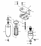
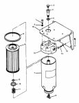
5. Go around to the Primary Fuel Filter assembly pictured below. Loosen Item #5, a brass bleeder petcock on first the Water Separator, (right side canister) and you should get fuel gushing out. Re-tighten the petcock. Then loosen Item #5 on the bottom of the Primary fuel filter. Fuel should gush out the system. Re-tighten the petcock.

1641900182057.png
6. Then look to the left and find the secondary fuel filter pictured below.

1641900706178.png

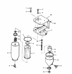
Loosen Item #3, a brass bleeder bolt. This should let any air trapped in the fuel system up to this point out. If bubbles are present, there is air. Let it all out. Re-tighten item #3. Wait 3-4 and loosen #3 again. When no bubbles are present, re-tighten #3.

7. Go around to the control cube and turn S7 off.
8. Turn S2 to the start position. Hold it there until the set starts, or 60 seconds has gone by. If it starts, it may stutter a bit but will smooth out. If no start, give the Starter motor 2-3 min to cool off, and try again. The gen set is well known to be a hard starter when the fuel system is dry. Repeat till it starts. Or if you think the batteries are starting to be weak. If that dont get it, say something
Open to read comments
 

Lugnuts

Active member
Steel Soldiers Supporter
323
239
43
Location
Myakka City, FL
So I read how to do this and Guyfang stated if this didn't work to write back.
Well it didn't work so I'm back.
I put new seals in the filters/ Did as per Operators Manual said /Switches and lights worked as mentioned/ No fuel

Afterward I looked on the electrical schematic and decided there where things that I didn't understand.
I went and checked the pumps themselves to see if they worked ie 24vdc Postive straight to the pump. They thumped quickly then slowed down as if under pressure but no fuel came out the bleeders/

There are several questions that I have that I could not find in the book/
One/ how does the Day Tank figure into this whole scenario?/ I anticipate an ass biting on this question
Secondly/ I have an external fuel source which comes in by the right of the fuel cap on the bottom/ Should this have a return line going back to the external tank? Mine doesn't.
Thirdly/ Does Steel Soldiiers have another TM for the repair of said generators. Another ass biting anticipated.

Thanks all
 

Guyfang

Moderator
Staff member
Moderator
16,766
24,082
113
Location
Burgkunstadt, Germany
Here we go. First off, where is your 3 way valve handle pointing. I know you said that all you did way change filters, but I am am not 100% sure if this set ran before you started changing filters. So, If your handle is not looking like this attached picture, move it. Simple problem that has stumped lots of folks, including me.

If the handle is in the right position, lets try this. You wrote this.
I went and checked the pumps themselves to see if they worked ie 24vdc Postive straight to the pump. They thumped quickly then slowed down as if under pressure but no fuel came out the bleeders/
So what I want you to do is look at the last electric fuel pump.
1643304894116.png
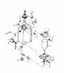
As you can see from the diagram, fuel is drawn from the tank, through the 3 way valve, to the B2, (first E-pump) then to and through the B3 and the fuel filter/strainer assy. Follow the hose on the output side of B3 over to the Strainer/filter assy and remove it. Put the end of the hose into a container. Push in CB1, (DC Control Circuit Breaker). Then place the S2, (start/run/stop switch) in the run position. Then place the S7, (Battle Short Switch in the Up/On position. At this time you should hear and feel the B2 &B3 come on. They should run FAST. Also know, that if the hose is not wedged into the container , the hose could come out, due to the out rush of fuel, and make a real big mess. If the pumps come on, and run fast, let them run and fill up your small, (QT will do) container. That should bleed out all air from the tank to the hose end. I use a glass container, so I can look at the fuel and see how funky it is. If this in fact happens, and you get fuel, then we need to go a step farther.

Turn off the pumps with S2. Leave the CB1 pushed in and S7 in the up position for the duration of this testing. Hook the hose back up. Turn the S2 back on.
1643305980183.png
Open the petcock (Item #5) on the fuel strainer. Fuel should come out at a very healthy stream. Use your handy container to catch it. If there is air bubbles, let it run until you only have fuel coming out. Then go to the other petcock on the filter to the left. Open it and see if fuel comes out. If so, go to the output side of the fuel filter/strainer head, (Item #17) and loosen the hose connected there. You should get maybe some air and then fuel. When its just fuel, tighten the hose up. Turn off the S2.
1643306567703.png
Trace the fuel line from the output side of the filter/strainer to the L2, (Fuel Shut Off Solenoid) item #15. Lossen the input hose, and turn on S2. Should get fuel coming out. Do have a large rag handy. Then tighten the input hose back up.If your fuel comes out, we now go to your mysterious DAY TANK.

The day tank is there for a real good reason. It keeps, (if its working right) the set from running out of fuel and emptying the fuel from the IP to the injectors, running bone dry. How does that work? The FL1 & FL2 switch. Item #16. There are two switches built into it. The switch can come with one or two floats on the switch. The one switch, FL1, turns the set off when it senses low fuel level in the day tank. That stops the set from running dry. The FL2 switch senses that the day tank is no longer full, and opens the L2 solenoid, to allow fuel to be pumped into the day tank, replenishing the supply of fuel in the day tank, from the set tank, (belly tank). When the FL2 senses that the tank is full, it closes L2.

Lesson over.

So, if you are getting fuel up to the L2, turn S2 off. Then remove the J33, (C-Plug on top of the FL1/FL2 switch. Then unscrew/remove the switch from the day tank. (Is the switch wet with fuel?) Screw the J33 back in. Here its good to have a helper. Hold the switch in one hand, and raise the float, or floats completely up. Have your trusted assistant place the S2 in the run position. Then lower the top float, (if there is two floats or just the one float) a bit, and the fuel pumps SHOULD come on. If not, continue to lower the float. If its a two float switch, just let the float go as far as it can. The pumps should come on, and fuel should fill the day tank. WARNING! If you pause to drink a beer, or something like that, the day tank WILL over flow in a hurry, as you have the day tank switch in your hand. It will happen faster then you can think about it. If not, we need to test first the Float switch, and then the CR-27 diode and the L2.

Let go this far, and you can look the test up in the -12 TM, (go to PDF reader page 161 and 162.) or tell me to stop, or walk you through the procedures.

Go for it!
 

Attachments

Lugnuts

Active member
Steel Soldiers Supporter
323
239
43
Location
Myakka City, FL
Here we go. First off, where is your 3 way valve handle pointing. I know you said that all you did way change filters, but I am am not 100% sure if this set ran before you started changing filters. So, If your handle is not looking like this attached picture, move it. Simple problem that has stumped lots of folks, including me.

If the handle is in the right position, lets try this. You wrote this.
I went and checked the pumps themselves to see if they worked ie 24vdc Postive straight to the pump. They thumped quickly then slowed down as if under pressure but no fuel came out the bleeders/
So what I want you to do is look at the last electric fuel pump.
View attachment 857092
As you can see from the diagram, fuel is drawn from the tank, through the 3 way valve, to the B2, (first E-pump) then to and through the B3 and the fuel filter/strainer assy. Follow the hose on the output side of B3 over to the Strainer/filter assy and remove it. Put the end of the hose into a container. Push in CB1, (DC Control Circuit Breaker). Then place the S2, (start/run/stop switch) in the run position. Then place the S7, (Battle Short Switch in the Up/On position. At this time you should hear and feel the B2 &B3 come on. They should run FAST. Also know, that if the hose is not wedged into the container , the hose could come out, due to the out rush of fuel, and make a real big mess. If the pumps come on, and run fast, let them run and fill up your small, (QT will do) container. That should bleed out all air from the tank to the hose end. I use a glass container, so I can look at the fuel and see how funky it is. If this in fact happens, and you get fuel, then we need to go a step farther.

Turn off the pumps with S2. Leave the CB1 pushed in and S7 in the up position for the duration of this testing. Hook the hose back up. Turn the S2 back on.
View attachment 857093
Open the petcock (Item #5) on the fuel strainer. Fuel should come out at a very healthy stream. Use your handy container to catch it. If there is air bubbles, let it run until you only have fuel coming out. Then go to the other petcock on the filter to the left. Open it and see if fuel comes out. If so, go to the output side of the fuel filter/strainer head, (Item #17) and loosen the hose connected there. You should get maybe some air and then fuel. When its just fuel, tighten the hose up. Turn off the S2.
View attachment 857094
Trace the fuel line from the output side of the filter/strainer to the L2, (Fuel Shut Off Solenoid) item #15. Lossen the input hose, and turn on S2. Should get fuel coming out. Do have a large rag handy. Then tighten the input hose back up.If your fuel comes out, we now go to your mysterious DAY TANK.

The day tank is there for a real good reason. It keeps, (if its working right) the set from running out of fuel and emptying the fuel from the IP to the injectors, running bone dry. How does that work? The FL1 & FL2 switch. Item #16. There are two switches built into it. The switch can come with one or two floats on the switch. The one switch, FL1, turns the set off when it senses low fuel level in the day tank. That stops the set from running dry. The FL2 switch senses that the day tank is no longer full, and opens the L2 solenoid, to allow fuel to be pumped into the day tank, replenishing the supply of fuel in the day tank, from the set tank, (belly tank). When the FL2 senses that the tank is full, it closes L2.

Lesson over.

So, if you are getting fuel up to the L2, turn S2 off. Then remove the J33, (C-Plug on top of the FL1/FL2 switch. Then unscrew/remove the switch from the day tank. (Is the switch wet with fuel?) Screw the J33 back in. Here its good to have a helper. Hold the switch in one hand, and raise the float, or floats completely up. Have your trusted assistant place the S2 in the run position. Then lower the top float, (if there is two floats or just the one float) a bit, and the fuel pumps SHOULD come on. If not, continue to lower the float. If its a two float switch, just let the float go as far as it can. The pumps should come on, and fuel should fill the day tank. WARNING! If you pause to drink a beer, or something like that, the day tank WILL over flow in a hurry, as you have the day tank switch in your hand. It will happen faster then you can think about it. If not, we need to test first the Float switch, and then the CR-27 diode and the L2.

Let go this far, and you can look the test up in the -12 TM, (go to PDF reader page 161 and 162.) or tell me to stop, or walk you through the procedures.

Go for it!
Thank you/ I printed it out and I will give see what gives tomorrow. I have a path I am following now.
 

Lugnuts

Active member
Steel Soldiers Supporter
323
239
43
Location
Myakka City, FL
That information on the fuel system is great! First off the handle was in the wrong position. I followed the procedure you outlined so well and I did not get fuel/ The pumps never turned on/ So I dropped the strainer bowl and removed the strainer (now in your procedure you said to removed the fuel line but I did not seeing I had to take the bowl off to get to the nut on the hose. If this is wrong please state it and will do as told) and turned on both switches ie the CB1 was in/ S2 was on/ S7 was on/ Red light for that was on/ and pumps did not run/
So I turn to Steel Soldiers for guidance.
 

Guyfang

Moderator
Staff member
Moderator
16,766
24,082
113
Location
Burgkunstadt, Germany
Lugs,

I wrote:
The day tank is there for a real good reason. It keeps, (if its working right) the set from running out of fuel and emptying the fuel from the IP to the injectors, running bone dry. How does that work? The FL1 & FL2 switch. Item #16. There are two switches built into it. The switch can come with one or two floats on the switch. The one switch, FL1, turns the set off when it senses low fuel level in the day tank. That stops the set from running dry. The FL2 switch senses that the day tank is no longer full, and opens the L2 solenoid, to allow fuel to be pumped into the day tank, replenishing the supply of fuel in the day tank, from the set tank, (belly tank). When the FL2 senses that the tank is full, it closes L2.

The pumps will not turn on unless the FL1 & FL2 switch tells it to. There are other factors that can also get in the way, but lets try this.

Push in CB1, place S7 in the on position.
Then remove the J33, (C-Plug on top of the FL1/FL2 switch. Get two paper clips. Bend them straight. Bend them in half. Holding the J33 in your hand, stick in the first paper clip into the A&B pins of J33. This should turn on the pumps, if the wire harness is good between the J33 and the pumps. Then place the second second paper clip into the C&D pins. This is the idot light. Do not let them touch or touch anything else. Place the S2 in the run position. The pumps should come on, and you should also get a LOW FUEL light on the A9, (fault indicator box). If that happens we need to test the FL1 &FL2 switch. If the pumps do not come on, then we need to test the L2.

Here is how to test the FL1 & Fl2 switch. You have to take it out. This info is in TM 9-6115-465-12, PDF Page # 161-162. I would read it once or twice to get the feel for the test.
c. Testing.
(1) Open the drain on the bottom of the day
tank and allow the fuel to drain into a suitable
container.
(2) Disconnect electrical connector from
day tank fuel level and low fuel cutoff switch.
(3) Using an ohmmeter, check for continuity
between switch connector pins A and B and
between pins C and D (figures FO-1 and FO-2).
(float or floats all the way down)
(4) Connect fuel solenoid connector and
float switch connector.
(5) Place START-RUN-STOP switch in RUN position and BATTLE SHORT switch in ON position.
(6) When fuel transfer pumps have refilled
day tank, return both switches to the original
position.
(7) Disconnect fuel solenoid connector and
float switch connector.
(8) Check for open circuit between pins
A and B and between pins C and D.
(Float or float up)
(9) Replace switch if the above continuity
requirements are not met.

If the switch tests good, the L2 is tested so:
You can continue to read the TM, the L2 testing follows the Switch testing, or, remove the L2. Its kinda a PITA, but doable. Then apply 24 VDC to the pins A&B on the L2. You should hear a click, or feel it move. If it works, then the CR-27 needs to be checked. Its the small black plastic thing next to the L2.

Testing CR-27.
(5) Check the diodes in the rectifier
assembly by placing the positive lead of an
ohmmeter on the red coded terminal and the
negative lead on one of the yellow coded terminals
(fig. 3-16). The ohmmeter should indicate a low
resistance.
(6) Reverse the ohmmeter leads. The
ohmmeter should read a high resistance (not
infinity).
(7) Perform the checks in paragraphs (5)
and (6) above using the opposite yellow coded
terminal.
If the test is not as stated in the book, CR-27 is bad.
If the colors are not visible, the red dot is the one in between the other two. There is a screw hole in three corners, and the one in the middle is the red terminal.
 

Lugnuts

Active member
Steel Soldiers Supporter
323
239
43
Location
Myakka City, FL
Lugs,

I wrote:
The day tank is there for a real good reason. It keeps, (if its working right) the set from running out of fuel and emptying the fuel from the IP to the injectors, running bone dry. How does that work? The FL1 & FL2 switch. Item #16. There are two switches built into it. The switch can come with one or two floats on the switch. The one switch, FL1, turns the set off when it senses low fuel level in the day tank. That stops the set from running dry. The FL2 switch senses that the day tank is no longer full, and opens the L2 solenoid, to allow fuel to be pumped into the day tank, replenishing the supply of fuel in the day tank, from the set tank, (belly tank). When the FL2 senses that the tank is full, it closes L2.

The pumps will not turn on unless the FL1 & FL2 switch tells it to. There are other factors that can also get in the way, but lets try this.

Push in CB1, place S7 in the on position.
Then remove the J33, (C-Plug on top of the FL1/FL2 switch. Get two paper clips. Bend them straight. Bend them in half. Holding the J33 in your hand, stick in the first paper clip into the A&B pins of J33. This should turn on the pumps, if the wire harness is good between the J33 and the pumps. Then place the second second paper clip into the C&D pins. This is the idot light. Do not let them touch or touch anything else. Place the S2 in the run position. The pumps should come on, and you should also get a LOW FUEL light on the A9, (fault indicator box). If that happens we need to test the FL1 &FL2 switch. If the pumps do not come on, then we need to test the L2.

Here is how to test the FL1 & Fl2 switch. You have to take it out. This info is in TM 9-6115-465-12, PDF Page # 161-162. I would read it once or twice to get the feel for the test.
c. Testing.
(1) Open the drain on the bottom of the day
tank and allow the fuel to drain into a suitable
container.
(2) Disconnect electrical connector from
day tank fuel level and low fuel cutoff switch.
(3) Using an ohmmeter, check for continuity
between switch connector pins A and B and
between pins C and D (figures FO-1 and FO-2).
(float or floats all the way down)
(4) Connect fuel solenoid connector and
float switch connector.
(5) Place START-RUN-STOP switch in RUN position and BATTLE SHORT switch in ON position.
(6) When fuel transfer pumps have refilled
day tank, return both switches to the original
position.
(7) Disconnect fuel solenoid connector and
float switch connector.
(8) Check for open circuit between pins
A and B and between pins C and D.
(Float or float up)
(9) Replace switch if the above continuity
requirements are not met.

If the switch tests good, the L2 is tested so:
You can continue to read the TM, the L2 testing follows the Switch testing, or, remove the L2. Its kinda a PITA, but doable. Then apply 24 VDC to the pins A&B on the L2. You should hear a click, or feel it move. If it works, then the CR-27 needs to be checked. Its the small black plastic thing next to the L2.

Testing CR-27.
(5) Check the diodes in the rectifier
assembly by placing the positive lead of an
ohmmeter on the red coded terminal and the
negative lead on one of the yellow coded terminals
(fig. 3-16). The ohmmeter should indicate a low
resistance.
(6) Reverse the ohmmeter leads. The
ohmmeter should read a high resistance (not
infinity).
(7) Perform the checks in paragraphs (5)
and (6) above using the opposite yellow coded
terminal.
If the test is not as stated in the book, CR-27 is bad.
If the colors are not visible, the red dot is the one in between the other two. There is a screw hole in three corners, and the one in the middle is the red terminal.
So here is what happened with that test
Holding the J33 in your hand, stick in the first paper clip into the A&B pins of J33. This should turn on the pumps, if the wire harness is good between the J33 and the pumps. Then place the second second paper clip into the C&D pins. This is the idot light. Do not let them touch or touch anything else. Place the S2 in the run position. The pumps should come on, and you should also get a LOW FUEL light on the A9, (fault indicator box). If that happens we need to test the FL1 &FL2 switch. If the pumps do not come on, then we need to test the L2.

So I jumped A-B and pumps did not run/ I jumped C-D and no light came on/ I then checked to see if any of the legs ABCD had power and found none/
I checked continuity at he float switch/ A-B had none/ C-D had continuity/
I pulled Day Tank Float switch and cleaned/ A-B had no continuity when the float was up or down/ C-C had continuity when down and not up/
But to repeat myself when jumping the connector at A-B/ Pumps did not run/

I did look for a Engine Run Wiring Schematic in the TM but did not find one.
Guidance please oh MEP 005 Master/
Lugnuts
 

Guyfang

Moderator
Staff member
Moderator
16,766
24,082
113
Location
Burgkunstadt, Germany
So I jumped A-B and pumps did not run/ I jumped C-D and no light came on/ I then checked to see if any of the legs ABCD had power and found none/
I checked continuity at he float switch/ A-B had none/ C-D had continuity/
I pulled Day Tank Float switch and cleaned/ A-B had no continuity when the float was up or down/
(No continuity on A&B, in any position means bad switch) C-C had continuity when down and not up/ (This would be a good reading.)
But to repeat myself when jumping the connector at A-B/ Pumps did not run/

I did look for a Engine Run Wiring Schematic in the TM but did not find one.


Was this a one or two float switch?
OK, at no pin on the canon plug J33, with the s2 in run, the S7 in the up position, the CB1 pushed in, did you have 24 VDC to ground. Right?
 

Lugnuts

Active member
Steel Soldiers Supporter
323
239
43
Location
Myakka City, FL
So I jumped A-B and pumps did not run/ I jumped C-D and no light came on/ I then checked to see if any of the legs ABCD had power and found none/
I checked continuity at he float switch/ A-B had none/ C-D had continuity/
I pulled Day Tank Float switch and cleaned/ A-B had no continuity when the float was up or down/
(No continuity on A&B, in any position means bad switch) C-C had continuity when down and not up/ (This would be a good reading.)
But to repeat myself when jumping the connector at A-B/ Pumps did not run/
I did look for a Engine Run Wiring Schematic in the TM but did not find one.


Was this a one or two float switch?
OK, at no pin on the canon plug J33, with the s2 in run, the S7 in the up position, the CB1 pushed in, did you have 24 VDC to ground. Right?
There were 2 floats on it/ and with s2 in run, the s7 in the up position, the CB1 pushed in there was no voltage what soever at the J33 plug that goes into the Floats
 

Guyfang

Moderator
Staff member
Moderator
16,766
24,082
113
Location
Burgkunstadt, Germany
You need to find another float in any case.

Now, we go into uncharted waters. The A27, ( special relay box).

Its the box in the rear bay with about a thousand C-Plugs hooked to it. Remove all the C-Plugs. Remove the 4, (If I remember right) hold down bolts. Take the A27 out. Remove the two screws that hold the cover and base together. The base get set off to the side. Look at the guts and see if there are any broken/ burnt wires. The look at the A5 card. million wires hooked to it. And broken parts? Burned parts? Signs of the card getting hot? Then remove the 4 nuts holding the A5 to the side of the box. Look at the back side of the card. Burns? Traces burnt through?
 
Top
AdBlock Detected

We get it, advertisements are annoying!

Sure, ad-blocking software does a great job at blocking ads, but it also blocks useful features of our website like our supporting vendors. Their ads help keep Steel Soldiers going. Please consider disabling your ad blockers for the site. Thanks!

I've Disabled AdBlock
No Thanks