• Steel Soldiers now has a few new forums, read more about it at: New Munitions Forums!

  • Microsoft MSN, Live, Hotmail, Outlook email users may not be receiving emails. We are working to resolve this issue. Please add support@steelsoldiers.com to your trusted contacts.

MEP-804A Overspeed

FLCarguy

Member
33
32
18
Location
Florida
Hi all,
I have the above set that I have had running well for over a year until about a month ago when it started to have the occasional overspeed then a hard overspeed whenever you tried to start it. Also at this time I noticed my voltage regulator was no longer working correctly and you could not control the voltage in the short time It would run. The situation is now, start the unit as normal, it revs very high, and shuts down via overspeed. Obviously it is actually in overspeed but I cannot figure out why. Things I have done so far.....

I replaced the voltage regulator with one from Kloppk and that is working great now... :)

1. Checked the transducer voltage at the Woodward controller, 2.46VAC.
2. Pulled and cleaned the transducer and reset it for the same voltage.
3. Replaced the transducer as the old one had a few scratches, tested voltage again at the controller.
4. Ran through all the troubleshooting tests for the woodward controller in the TM and all pass except it puts out a very high voltage to the actuator. It immediately shoots to somewhere in the 20V range before the unit shuts down.

To me the actuator seems to be ok as when you put power to it, it moves, but when they fail do they just go to max travel? I would assume they would just not work but who knows. So I think my problem is with the controller or the actuator. The actuator is made by woodward.

One other thing to note is when the unit starts the frequency gauge on the front rails out, then bounces around a bit but never back to "normal". Unit is set for 60hz but does the same thing at 50hz. I can only run it about 10 seconds in this condition.

Regards,
Jason
 

loosegravel

Just a retired mechanic who's having fun!
504
890
93
Location
Enumclaw, Washington
Hello, I also have in my possession a MEP-804A. When I brought it home from auction about 4 months ago I too had some over-speed issues. The members here in this forum are always so willing to help. My unit had a couple of gauges replaced at some point before I got it. They left the shipping springs (for lack of better description) on the back of the gauges. That was one problem. The other thing that I did based on the recommendations from this great forum is simply cycle the S1 and the S6 switches several times back and forth. This is done with the unit off, and it’s probably not a bad idea to have the batteries disconnected for the S1. The contacts in these switches are prone to corrosion in time from the elements. Also, my unit has the less desired plastic S1. They’re prone to fail. One more comment. I’ve had faults on other units such as the MEP-803A 10kw. I have checked and double checked the terminal strip screws, wiggled the relays and frequency trip switches with success. They’re also prone to some corrosion in higher moisture climates. Good luck, and I’m sure that someone else will chime in with some more technical information here!
 

FLCarguy

Member
33
32
18
Location
Florida
Hello, I also have in my possession a MEP-804A. When I brought it home from auction about 4 months ago I too had some over-speed issues. The members here in this forum are always so willing to help. My unit had a couple of gauges replaced at some point before I got it. They left the shipping springs (for lack of better description) on the back of the gauges. That was one problem. The other thing that I did based on the recommendations from this great forum is simply cycle the S1 and the S6 switches several times back and forth. This is done with the unit off, and it’s probably not a bad idea to have the batteries disconnected for the S1. The contacts in these switches are prone to corrosion in time from the elements. Also, my unit has the less desired plastic S1. They’re prone to fail. One more comment. I’ve had faults on other units such as the MEP-803A 10kw. I have checked and double checked the terminal strip screws, wiggled the relays and frequency trip switches with success. They’re also prone to some corrosion in higher moisture climates. Good luck, and I’m sure that someone else will chime in with some more technical information here!
Hi Loosegravel,
I think you may be on the right track as, I cannot find anything out of the ordinary with my controller and it was working fine up until this. I will have to check all the connections and relay sockets and for sure I am in a humid environment! I did test the frequency pot input to the controller yesterday and it was very linear and was from 10ohms to 4.83K and the book says 5k so I figured that was close enough.
 

FLCarguy

Member
33
32
18
Location
Florida
Update, I have checked all the connections I can get to, removed all the relays, tapped them, tested them, put them back, did the testing for the Woodward controller again and it passes all the tests in the TM. I have reset the pickup transducer about 10 times, I have 2.8VAC now at the controller while cranking manually. Today I removed the Woodward controller suspecting it was bad but visually it looks fine. Not burned up and it passes the TM tests for being good. Those tests also test the signals from S1 which test correctly. So my thoughts now are maybe the actuator is bad? Is it possible for it to fail and just go to full throttle? Remember when I test the output of the Woodward to the actuator it goes to max voltage of 22-24 volts when it starts right before tripping the overspeed. I am wondering if I could disconnect the actuator and see if the Woodward unit was putting out the correct signal with it disconnected? Is this a valid test? I do have a variable power supply I could use to test the actuator but I am not sure if it is just a voltage or PWM? Does anyone know? You can get a cheap PWM driver off amazon so that might be worth it too.

Thanks,
Jason
 

Guyfang

Moderator
Staff member
Moderator
16,696
23,904
113
Location
Burgkunstadt, Germany
Update, I have checked all the connections I can get to, removed all the relays, tapped them, tested them, put them back, did the testing for the Woodward controller again and it passes all the tests in the TM. I have reset the pickup transducer about 10 times, I have 2.8VAC now at the controller while cranking manually. Today I removed the Woodward controller suspecting it was bad but visually it looks fine. Not burned up and it passes the TM tests for being good. Those tests also test the signals from S1 which test correctly. So my thoughts now are maybe the actuator is bad? Is it possible for it to fail and just go to full throttle? (Highly unlikely.) Remember when I test the output of the Woodward to the actuator it goes to max voltage of 22-24 volts when it starts right before tripping the overspeed. I am wondering if I could disconnect the actuator and see if the Woodward unit was putting out the correct signal with it disconnected? Is this a valid test? (You can apply 24 VDC to the A6 and the gen set should run.) I do have a variable power supply I could use to test the actuator but I am not sure if it is just a voltage or PWM? Does anyone know? You can get a cheap PWM driver off amazon so that might be worth it too.

Post a video of it in start mode. When it just clicks, and when it starts. The click you hear on attempted start, is probably the K22. You are trying to shotgun the problem. Concentrate on one thing. Starting the set. In all probability, that will fix your other problem also. Perhaps the attachment will help. The start circuit is fairly simple.


Thanks,
Jason
 

Attachments

FLCarguy

Member
33
32
18
Location
Florida
Hi GuyFang,
Thanks for the reply, I am not sure if I am not being clear or I mis-understand what you are saying. The generator starts, and runs, but only at full throttle. The controller is not controlling anything. Just puts battery voltage to the actuator at pins 9 and 10. The TM says it should be 16-17v when starting and 7-8vdc when running. Mine just goes to 22 or more and stays there. I have bypassed the overspeed to let it run a second longer but obviously can't do that long. That is the only test that fails when you test A5. I can take a video when I get home, on the road fixing someone else problems for a few days. :)
 

loosegravel

Just a retired mechanic who's having fun!
504
890
93
Location
Enumclaw, Washington
Is is possible to disconnect the R2 variable resistor for the frequency adjustment before starting the engine? Will it run that way? I’ve had to replace the R1 voltage adjustment variable resistor on one of the 15KW units that’s gone through my hands in the past. It had been turned past the stop. Anyway, just thinking of a way to eliminate the R2 as the problem.
 

FLCarguy

Member
33
32
18
Location
Florida
Test R2 IAW the TM. That would be simpler then replacing it. And you would KNOW if its good or bad.
Sorry, been out on the road forever and still out but did want to respond. One of the tests in the TM is to test the R2 pot wiper input to the controller. It goes from 10ohms to almost 5k pretty linearly. it is also 5k on the ends. Is there anything else to test with it?
 

FLCarguy

Member
33
32
18
Location
Florida
On thing I did not recall what the result was anyways, was to put 24V on the controller terminal 3 directly from the battery and see if somehow it was dropping power from S2 when it went to run.
 

FLCarguy

Member
33
32
18
Location
Florida
Hi all,
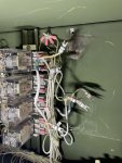
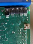
Finally got back home and started in on the generator. I was about to put the regulator back into the machine and found this burn mark on the back panel, not sure how I did not see it before. I took pictures of the back panel, and the back of the regulator. The burn mark is about 2.5cm below the upper left bolt exactly behind these transistors but looking at them they don't look like they could have caused that burn mark. Also I removed the silicon over them so I could identify what model they were. Before that they all looked about the same. So my question is, do you think this regulator caused that burn mark or an older one that has since been replaced? If it was this one, I can repair it but does anyone know what could cause this or have a schematic of the actual woodward controller? I don't want it to happen again.

Thanks,
Jason
 

Attachments

FLCarguy

Member
33
32
18
Location
Florida
Hi all,
Finally got back home and started in on the generator. I was about to put the regulator back into the machine and found this burn mark on the back panel, not sure how I did not see it before. I took pictures of the back panel, and the back of the regulator. The burn mark is about 2.5cm below the upper left bolt exactly behind these transistors but looking at them they don't look like they could have caused that burn mark. Also I removed the silicon over them so I could identify what model they were. Before that they all looked about the same. So my question is, do you think this regulator caused that burn mark or an older one that has since been replaced? If it was this one, I can repair it but does anyone know what could cause this or have a schematic of the actual woodward controller? I don't want it to happen again.

Thanks,
Jason


I am back on the road, when I posted those pictures and now that I look at them closely I think the burned spot is below the bolt for the terminal strip more than under the transistors. I wish I had the controller in front of me.
 

FLCarguy

Member
33
32
18
Location
Florida
No, I do not think its was from the A1. You have some wire damaged wires there. That may have something to do with it. But no marks on the A1.
So back at it, I am finally home and went over all the wires in the area, none are damaged, or burned, and all ohm out well, took all the harnesses apart near there to inspect each wire. Also after putting the A1 back it is clear that the burn area is under the A1 where there are no wires on my machine. So I decided to do a little test, I was going to run the governor actuator off a 6VDC power supply I had and then take some readings from the A1. Well my power supply only goes to 6A and that is not enough to engage the actuator which I find strange? Does anyone know the current draw for the solenoid in there? My sticker is worn away on the actuator itself. I was able to get it to actuate with a 12V battery but that is too much speed for the unit. I am going to try a beefy 6V battery tomorrow. I still at this point suspect A1 governor.
 

FLCarguy

Member
33
32
18
Location
Florida
I just found the data sheet online, it looks like it draws 2.5A in steady state with 12V. So with 6V it would draw 5-6A so might be normal in this test. Lets see how the battery does.
 

FLCarguy

Member
33
32
18
Location
Florida
Follow up, I was able to resolve this issue with a new A5 Governor controller. The transistors that control the voltage to the solenoid failed. Everything else on it was good. So now the overspeed is fixed, the genset is running good, I can control the speed with the freq dial, however I still have another issue..... I will start a new thread on that. Thanks for all the help!
 
Top
AdBlock Detected

We get it, advertisements are annoying!

Sure, ad-blocking software does a great job at blocking ads, but it also blocks useful features of our website like our supporting vendors. Their ads help keep Steel Soldiers going. Please consider disabling your ad blockers for the site. Thanks!

I've Disabled AdBlock
No Thanks