• Steel Soldiers now has a few new forums, read more about it at: New Munitions Forums!

  • Microsoft MSN, Live, Hotmail, Outlook email users may not be receiving emails. We are working to resolve this issue. Please add support@steelsoldiers.com to your trusted contacts.

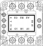
MEP-802A K1 Terminal Layout

goat4hooves

New member
14
3
3
Location
Idaho
Thank you to all who share their knowledge about these generators. I have learned a lot buy reading through the forum.

I won a generator in July. During the initial inspection I noticed many wires that were not connected to anything. This set me on the path of checking and chasing out every wire. It is a good thing because it was/is horribly wired.

What is the terminal layout of the K1 AC Circuit Interrupter Relay? I have provided a picture of what mine looks like. The numbering does not match what is called out in TM 9-6115-641-24, 2-61-3 or the F0-2 Wiring Diagram Sheet 5.

Any help will be greatly appreciated. Thank you in advance.
 

Attachments

Guyfang

Moderator
Staff member
Moderator
16,761
24,067
113
Location
Burgkunstadt, Germany
Here is a copy of what K1 looks like hooked up. Every wire there is marked. So you cant go wrong. Now this is just me, but I would completely disconnect EVERY wire from the K1. I would unscrew the K1 from the bottom of the control panel. Take it out, wipe it down. LOOK at the numbers on the K1, like A1, B1, C1, X, Y and so on. Then look at the page I just attached to this message. And I would print it out, so you can have it to hand, when you attach the wires back to the K1. Then screw the K1 back down to the control panel. Reattach the wires one at a time. Take your time. Get it right. Follow the plan. Do NOT attempt to follow the numbers some one wrote on the wires. Everything is labeled. Its easy, trust me.

I hate to tell you this, but I would, if this was my gen set, do the same thing to the S8. THAT, is a PITA. But it looks like someone screwed the pooch here. Do the K1 first. Think of it as a warm up.

There are two terminal safety covers, and 4 each retaining screws missing from the K1.


View attachment 696342
 

goat4hooves

New member
14
3
3
Location
Idaho
Guyfang, thanks for the advice and diagram it is much appreciated.

I did remove K1 and wiped it down. Could not find any markings on the K1 annotating the terminal layout. There were two spots where decals had once been, but no where to be found.

Since I had it out I decide to take the dust covers off, clean the contacts, and inspect the internal wiring. From there,I figured out what I think is the correct terminal layout. Does this look like the proper terminal assignment to you guys?

I will also inspect S8. What order is the L1, L2, L3 terminal layout? It is hard for me to decipher from the wiring diagram. I assume the L0 terminal is on the bottom of the switch. Is that correct?
 

Attachments

Guyfang

Moderator
Staff member
Moderator
16,761
24,067
113
Location
Burgkunstadt, Germany
Yes, LO is at the bottom.

At the end of the day, as long as you get the L1 input wire hooked to the K1, across from the L1 output wire, and so on, that part really isn't all that important. Then you need to find X1 and Y1, the coil connections for K1. The other two connections, 11 & 12 are for the DS7 light. 11 and 12 are normally open connection. When the K1 is powered up, the connection closes.
 

goat4hooves

New member
14
3
3
Location
Idaho
Guy, thanks again. I had to sit and think on what you said about L1,L2, and L3. It makes sense now.

The good news is that everything is now wired properly and the generator is making power on all 3 different settings on S8.
 

goat4hooves

New member
14
3
3
Location
Idaho
Here is another plug for reading and studying the manuals in depth. I do not know how I missed it but L1, L2, L3, and L0 S8 locations are clearly identified on F0-1, FP-1.

If it had been a snake it would have jumped out and bit me!
 

Guyfang

Moderator
Staff member
Moderator
16,761
24,067
113
Location
Burgkunstadt, Germany
Goat,

You ain't the first, and sure won't be the last to learn that. I am dyslexic. Reading the schematics has always been tough for me. I learned to go over them several times and always have a pen and paper at hand. Then, look ONE MORE TIME, just to make sure I hadn't screwed it up YET AGAIN. The fact is, practice makes perfect. And You seem to be on top of this.
 

Guyfang

Moderator
Staff member
Moderator
16,761
24,067
113
Location
Burgkunstadt, Germany
Its possible to clean them up. But they will never be as good as new. This kind of damage can often occurs when people shut the gen set off, without turning the load off first. For peace of mind, I would get a new K1.

Should you have other questions about your gen set, it would be better for you and us, if you started your own thread. That way we can keep track of what is what, and who is who.
 

Ray70

Well-known member
2,592
5,907
113
Location
West greenwich/RI
As a side note, if you don't find any markings on your K1, I think the reason is that some K1 contactors originally had a plastic cover on the top that covered the wiring connections. If I recall, that cover had the terminal identification numbers printed on it ( A1 A2 11,12 etc.. )
 
Top
AdBlock Detected

We get it, advertisements are annoying!

Sure, ad-blocking software does a great job at blocking ads, but it also blocks useful features of our website like our supporting vendors. Their ads help keep Steel Soldiers going. Please consider disabling your ad blockers for the site. Thanks!

I've Disabled AdBlock
No Thanks