- 1,102
- 1,633
- 113
- Location
- Wilson County, Texas
Everyone,
I know there are a few threads on this already. Have read through them & learned from them. Used that & have troubleshooted, but am still a but stumped. My situation is a little different, so I will try to consolidate what I have done as much as possible so that I can get some input here.
SITREP... My MEP 803A is a 2011 manufacture. It appears to sat inside a warehouse as it looks virtually new inside & out. The scraps/dents are from me or the state level surplus that handles it. Had 31 hours on the meter. No reset. All the extras inside seemed to never be touched. Fuel & fluid was left in it, so the floats were sticky. That was the only issue with it when I got it. Removed & cleaned the double float switch, replaced the sender, fresh fluid with some ATF, and it runs very nice. Had oil & coolant that was not to old in it already. Batteries were not old, Optima. So, mechanically it is good. I planned to run it through my 6 hour load test, then do a full filter/fluid swap & call it ready. Now, here we are.
After warming it up, loaded it to 5,000 watts with 240v electric heater. 240v single phase setting. Added the second one. Then, a 1,750 watts 110v heat gun. Then, a 1,500 watts 110v heater. One of the 240v leads had a power distribution box. It was burning off great. I suspect this generator was never even really run under load, just started to charge the batteries over the years. It barley has the paint burned off the exhaust manifold. After a few minuets, walked away to come back out & see the overload. Was a bit surprised as it seemed to be fine, but figured maybe it was due to one leg being loaded. Not the case. Basically, even with the even 10,000 watts, it will overload. With battle short on, it will go all day. With the S6 in a position for 3 phase, it will go all day.
Here is what I did for troubleshooting.
Used CRC contact cleaner liberally on S6 & S8. They appear perfectly clean, but figured I would. I know the forum recommends the DetoxIT, so I have some on the way.
EDIT: Forgot to put that I swapped the S14 for a known good. No change.
Checked loops on the CT. All are good. 4.
Checked connections on S6. Found some of my wires 6's have 8's, but they otherwise match up at the other end. Same on S8. For example, 187A should be 167A. Error from the manufacturer.
Disconnected J6 & J7. Both are tight & clean. Bright gold. No green.
Check tightness on all connections. Overall, I did find a lot of things I'd say were loose on this generator. Biggest hint to this was a single TB screw in the bottom of the generator. I was really hoping this was going to be my gremlin, but it wasn't. It was from TB4-7 that is blank. But, TB4 had fallen off the generator and was just loose!! Secured that. Was hoping THAT would be my issue, but no. Found a loose connection due to a semi stripped screw on K8-6. Replaced it. No change by tightening connections on just about all connections involved.

Used my multimeter and a Kill A Watt to calibrate the gauges. The frequency & voltage were off a bit. Wasn't sure if this could contribute. Set to 60hz and 240v exactly then adjusted the gauges.
I replaced R11 with a known good. I know they should all be de-soldered to be checked. I didn't do this yet to them all but when checking against other units I have, this one gave me a rather off ohms reading so I did it. After it being removed, it read fine. So, don't do this.
In one of the posts, I found @kloppk Post the proper voltages for R10, R11, & R12. Here is where I'm seeing issue.
R10 0%-1.3v 50%-2.1v 100%-4.3v 115%-5v
R11 0%-1.3v 50%-2.1v 100%-4.3v 115%-5v
R12 0%-1.4v 50%-4.2v 100%-9.5v 115%-9.5v
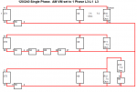
I know at 0%, it should be 0v. But, I think the big issue is on that R12. That imbalance is there. So, using this schematic I got from another post, I looked more in depth on that leg.

The CT produces the voltage to these, so I started there. It goes through CT3. I have wires 003A10 & 009A10 in there looped 4 times. Removed the C1 & C3. Has continuity. Cleaned everything & attached. At the point I am at when typing this, I need to let my CRC contact cleaner dry before trying to run again after cleaning.
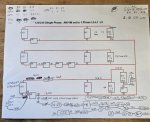
I took out my hardback TM with the wire diagrams and went through everything on that leg. WOW, it's a lot. I have the older style switches, so it should match perfectly the diagram with the numbers. I used the diagram from above, printed it, and started doodling to fill the details in. Here is is;

As I'm typing this, my next step is to go touch & check each wire in that leg. At this point, I suspect a bad CT or something in the plug side of J6/J7. Before I start going wild with ripping major stuff out & throwing parts at it, I wanted to see if I am missing something obvious since I'm kind of in deep & a bit frustrated. Been at this almost two days now when I expected to be giving this the okay & having the trailer setup again & on to better things yesterday afternoon. If I think of something I did & didn't put in this post, I will come back to edit.
Just a few pictures to show how clean it is;


I know there are a few threads on this already. Have read through them & learned from them. Used that & have troubleshooted, but am still a but stumped. My situation is a little different, so I will try to consolidate what I have done as much as possible so that I can get some input here.
SITREP... My MEP 803A is a 2011 manufacture. It appears to sat inside a warehouse as it looks virtually new inside & out. The scraps/dents are from me or the state level surplus that handles it. Had 31 hours on the meter. No reset. All the extras inside seemed to never be touched. Fuel & fluid was left in it, so the floats were sticky. That was the only issue with it when I got it. Removed & cleaned the double float switch, replaced the sender, fresh fluid with some ATF, and it runs very nice. Had oil & coolant that was not to old in it already. Batteries were not old, Optima. So, mechanically it is good. I planned to run it through my 6 hour load test, then do a full filter/fluid swap & call it ready. Now, here we are.
After warming it up, loaded it to 5,000 watts with 240v electric heater. 240v single phase setting. Added the second one. Then, a 1,750 watts 110v heat gun. Then, a 1,500 watts 110v heater. One of the 240v leads had a power distribution box. It was burning off great. I suspect this generator was never even really run under load, just started to charge the batteries over the years. It barley has the paint burned off the exhaust manifold. After a few minuets, walked away to come back out & see the overload. Was a bit surprised as it seemed to be fine, but figured maybe it was due to one leg being loaded. Not the case. Basically, even with the even 10,000 watts, it will overload. With battle short on, it will go all day. With the S6 in a position for 3 phase, it will go all day.
Here is what I did for troubleshooting.
Used CRC contact cleaner liberally on S6 & S8. They appear perfectly clean, but figured I would. I know the forum recommends the DetoxIT, so I have some on the way.
EDIT: Forgot to put that I swapped the S14 for a known good. No change.
Checked loops on the CT. All are good. 4.
Checked connections on S6. Found some of my wires 6's have 8's, but they otherwise match up at the other end. Same on S8. For example, 187A should be 167A. Error from the manufacturer.
Disconnected J6 & J7. Both are tight & clean. Bright gold. No green.
Check tightness on all connections. Overall, I did find a lot of things I'd say were loose on this generator. Biggest hint to this was a single TB screw in the bottom of the generator. I was really hoping this was going to be my gremlin, but it wasn't. It was from TB4-7 that is blank. But, TB4 had fallen off the generator and was just loose!! Secured that. Was hoping THAT would be my issue, but no. Found a loose connection due to a semi stripped screw on K8-6. Replaced it. No change by tightening connections on just about all connections involved.

Used my multimeter and a Kill A Watt to calibrate the gauges. The frequency & voltage were off a bit. Wasn't sure if this could contribute. Set to 60hz and 240v exactly then adjusted the gauges.
I replaced R11 with a known good. I know they should all be de-soldered to be checked. I didn't do this yet to them all but when checking against other units I have, this one gave me a rather off ohms reading so I did it. After it being removed, it read fine. So, don't do this.
In one of the posts, I found @kloppk Post the proper voltages for R10, R11, & R12. Here is where I'm seeing issue.
R10 0%-1.3v 50%-2.1v 100%-4.3v 115%-5v
R11 0%-1.3v 50%-2.1v 100%-4.3v 115%-5v
R12 0%-1.4v 50%-4.2v 100%-9.5v 115%-9.5v
I know at 0%, it should be 0v. But, I think the big issue is on that R12. That imbalance is there. So, using this schematic I got from another post, I looked more in depth on that leg.

The CT produces the voltage to these, so I started there. It goes through CT3. I have wires 003A10 & 009A10 in there looped 4 times. Removed the C1 & C3. Has continuity. Cleaned everything & attached. At the point I am at when typing this, I need to let my CRC contact cleaner dry before trying to run again after cleaning.
I took out my hardback TM with the wire diagrams and went through everything on that leg. WOW, it's a lot. I have the older style switches, so it should match perfectly the diagram with the numbers. I used the diagram from above, printed it, and started doodling to fill the details in. Here is is;

As I'm typing this, my next step is to go touch & check each wire in that leg. At this point, I suspect a bad CT or something in the plug side of J6/J7. Before I start going wild with ripping major stuff out & throwing parts at it, I wanted to see if I am missing something obvious since I'm kind of in deep & a bit frustrated. Been at this almost two days now when I expected to be giving this the okay & having the trailer setup again & on to better things yesterday afternoon. If I think of something I did & didn't put in this post, I will come back to edit.
Just a few pictures to show how clean it is;


Last edited:


